

Packoff Nipple
Active Publication Date: 2006-05-18
ISOLATION EQUIP SERVICES
View PDF14 Cites 13 Cited by
- Summary
- Abstract
- Description
- Claims
- Application Information
AI Technical Summary
Benefits of technology
[0009] In one embodiment, the packoff nipple provides one or more elastomeric sealing rings adapted to seal the annular space in response to an actuating mechanical force, preferably pressure-induced, exerted against each sealing ring. Furthermore, the packoff nipple is adapted to axially compress the sealing rings in response to increasing pressure. Upon equalization of the pressure differential across the packoff nipple, the sealing rings substantially return to their pre-actuated shape, thereby permitting the packoff nipple to be safely extracted from the well pipe without incurring damage to the sealing rings. The packoff nipple can be used for any operations that introduce elevated pressure into a well where it is desired to isolate the annular space. For example, one or more packoff nipples can be fit on the end of a mandrel of a wellhead isolation tool to isolate an uphole wellhead from high pressures and corrosive materials used downhole of the packoff nipples during well stimulation.
[0011] The sealing ring assembly preferably includes a plurality of stacked sealing rings to provide a redundancy in sealing. The sealing ring assembly can further include rigid spacers positioned between the actuator and an adjacent sealing ring and between adjacent sealing rings. The rigid spacers may assist in keeping the sealing rings perpendicular to the tubular body for tripping in and out of the well pipe and in equalizing actuating forces exerted across the downhole face of a sealing ring.
[0014] Further adaptations to the packoff nipple that provide functional and structural advantages for any packoff nipple are also described. For example, the uphole stop can have a concave stop surface that urges or constrains a top of an adjacent sealing ring or any other suitable sealing member radially inwardly to avoid extrusion. In addition, an improved sleeve suitable for use with any sealing member, such as a packer cup, intended to be slidably fit around a tubular body is also provided, whereby the sleeve includes an upper radial compression surface to form a supplemental seal between the radial compression surface and the tubular body.
Problems solved by technology
Stimulation fluid may comprise components such as acid, sand, and energized carbon dioxide and nitrogen gases that, alone and under high pressures, can be damaging to the structural integrity and internal surfaces of a wellhead assembly that is installed at the top of a well casing or tubing.
In general, elastomeric seals of prior art packoff nipples are susceptible to damage during well tubing or casing entry or exit, particularly when the packoff nipple must pass areas of restricted internal diameter.
This can be particularly problematic with extruded seals, which typically become permanently deformed when actuated.
Prior art packoff nipples are also prone to seal pre-activation during well tubing entry whereby the seals are forced from their protective running-in condition to an actuated condition, thereby increasing the likelihood of seal damage.
In any case, damage to the seals does not permit the packoff nipple to be reused and also results in damaged seal material being left in the well, thereby increasing the cost of operations.
Other difficulties encountered by prior art packoff nipples include seal failure due to seal damage by exposure to extreme temperatures associated with CO2 and N2 stimulating fluids, as well as due to misalignment of the packoff nipple in the well tubing.
Method used
View moreImage
Smart ImageViewing Examples

Examples
example 1
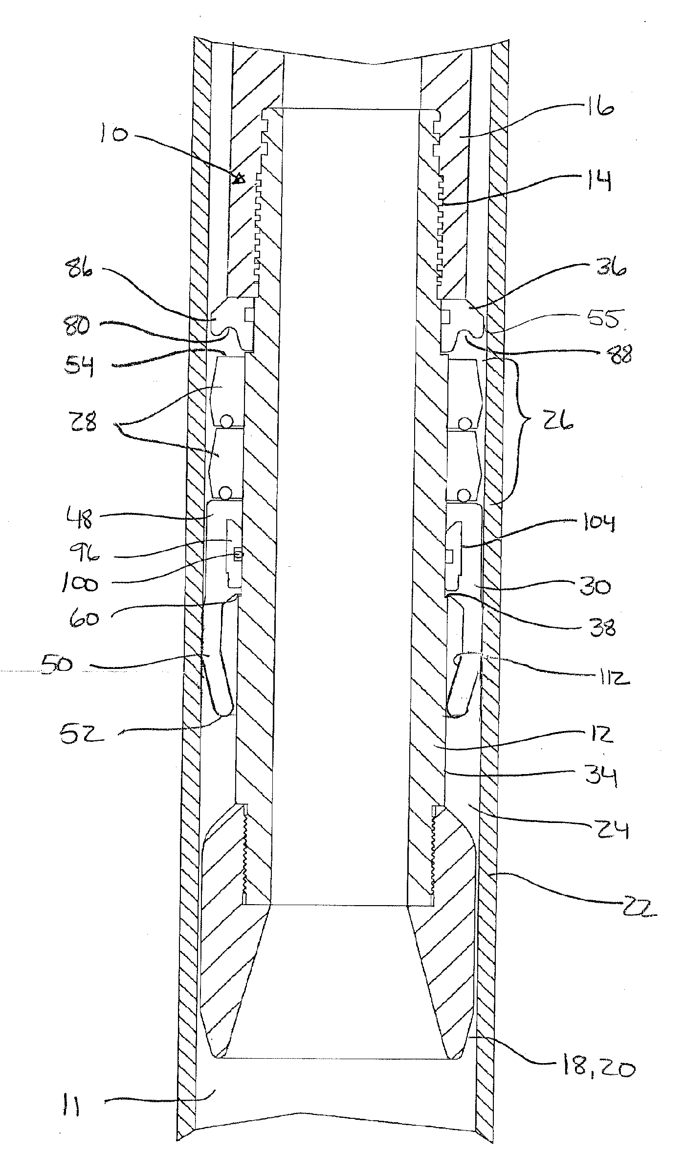
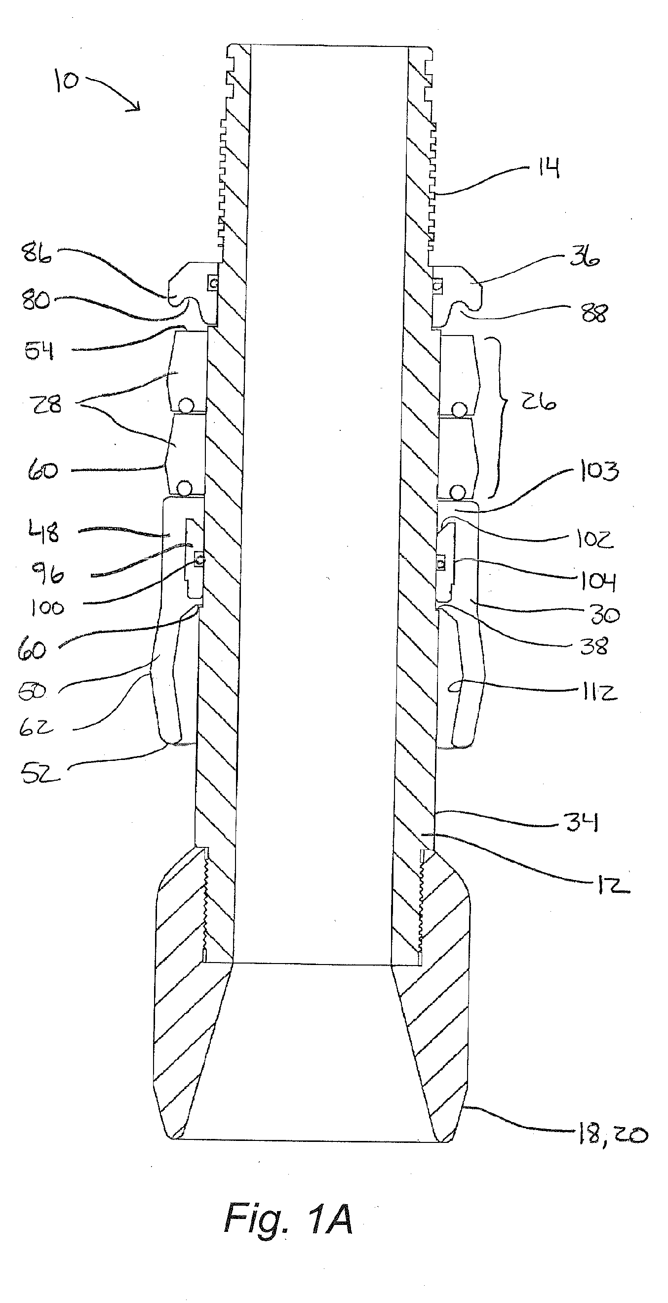
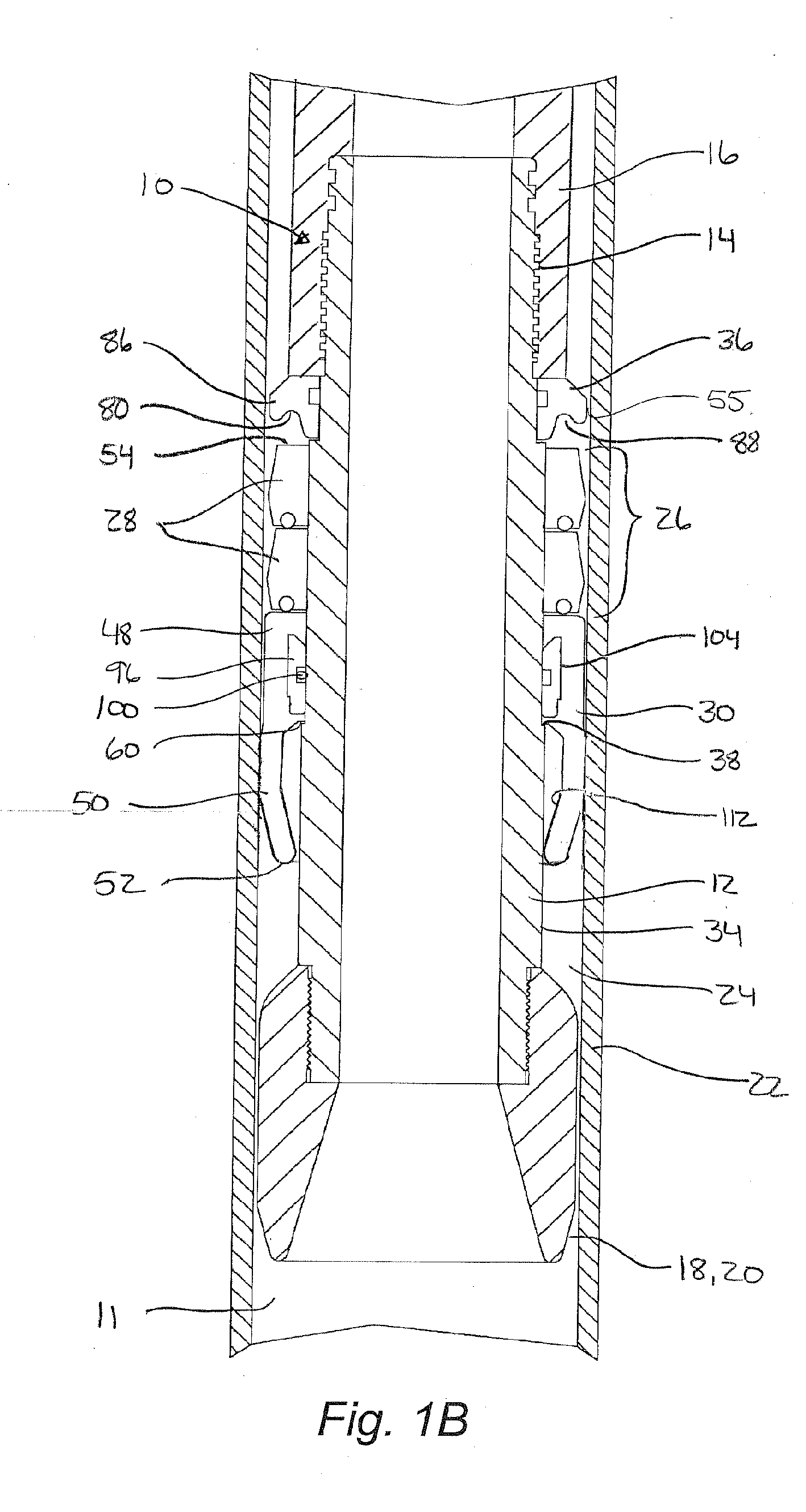
[0065] The following exemplifies the outer diameters of various components of a packoff nipple 10 according to the present invention installed in well pipe 22 of an inner diameter of 2.441 inches.
ComponentO.D. (inches)Tubular body 121.870Uphole stop 362.370Sealing ring (midsection) 622.390Spacer 322.370Packer cup skirt (midsection)2.50064Packer cup skirt (bottom) 522.360Bullnose 202.395
example 2
[0066] The following exemplifies the outer diameters of a various components for a packoff nipple 10 according to the present invention installed in well pipe of an inner diameter of 4.892 inches.
Login to View More PUM
 Abstract
A packoff nipple is provided for sealing an annular space in a well pipe. The packoff nipple generally comprises a tubular body and a sealing assembly positioned around the tubular body and axially moveably thereon. A stop restrains the sealing assembly from extruding in to the annular space. The sealing assembly includes one or more elastomeric sealing rings having a circumferential groove formed in a downhole face. An axially moveable actuator, preferably a packer cup, engages the sealing ring assembly to causes at least an expansion portion of the sealing rings to expand radially outwardly to seal the annular space and the sealing ring assembly to contact the uphole stop. The sealing rings are axially compressed between the uphole stop and the actuator to further expand the sealing rings. Preferably the uphole stop is concave to urge the sealing rings away from the well pipe and thus further avoid extrusion. As the sealing rings are not extruded past the uphole stop or otherwise permanently deformed, the packoff nipple is reusable and thereby cost-effective.
Description
FIELD OF THE INVENTION [0001] The invention relates to a packoff nipple and structures supporting packoff nipples and more particular to a non-extruding packoff nipple and arrangement thereof for sealing an annular space in a well pipe. BACKGROUND OF THE INVENTION [0002] It is often the case that wells require stimulation to restart or enhance hydrocarbon flow. Such stimulation typically involves pumping stimulation fluid into the hydrocarbon bearing formation under pressure. Stimulation fluid may comprise components such as acid, sand, and energized carbon dioxide and nitrogen gases that, alone and under high pressures, can be damaging to the structural integrity and internal surfaces of a wellhead assembly that is installed at the top of a well casing or tubing. In other instances, it is preferred to localize the effects of elevated pressure in a well. [0003] To protect a wellhead from damage including from high pressures and corrosive or erosive materials used during stimulation ...
Claims
Login to View More Application Information
Patent Timeline
 IPC IPC(8): E21B33/12
CPCE21B33/068E21B33/1216
InventorCHEREWYK, BORIS (BRUCE)
OwnerISOLATION EQUIP SERVICES