Aquarium

Inactive Publication Date: 2006-05-18
HOCHANG BRADLEY EARL +1
View PDF11 Cites 9 Cited by
  • Summary
  • Abstract
  • Description
  • Claims
  • Application Information

AI Technical Summary

Benefits of technology

[0021] In another exemplary embodiment of the present invention, a second filtration system with at least a portion of the filtration system may be located in the second side cavity of the container. The second filtration system acts to filter the water similar to the filtration system. In an exemplary embodiment of the present invention, the filtration system and the second filtration system may share the vacuum pump. In addition, the filtration system and second filtration system may direct the filtered water into the lower cavity and through the plurality of holes located in the first plate and into the main cavity.
[0022] In another exemplary embodiment of the present invention, a fourth plate may be located in said lower cavity to separate said lower cavity into a first lower cavity and a second lower cavity. The fourth plate provides a barrier to fluid communication between the first lower cavity and the second cavity along the length or depth, or both, of the container. The fourth plate further provides limited fluid communication between the first side cavity and the second side cavity along a portion of the length or depth, or both of the container. In an exemplary embodiment of the present invention, the limited fluid

Problems solved by technology

Further, because of deficiencies in current filtration design, it has therefore been necessary to maintain a large volume of water to act as a buffer in both fresh and salt water aquariums so to avoid poisoning of the aquatic animals.
Air is forced by the pump to the air stones thereby forcing air bubbles to travel up through the tubes to the water surface creating turbulence or current.
A biological filter does not, however, remove all chemical wastes and by itself is considered a very inefficient form of filtration.
While some of the filters described above improve the water quality, they still do

Method used


Image

  • Aquarium
  • Aquarium
  • Aquarium

Examples


Embodiment Construction

[0028] In general, the present invention can be described as a novel aquarium filter that requires a minimal amount of water and, additionally, reduces the space required for other components to facilitate a compact design and provide an improved viewable area.

[0029] Referring now to the figures, in which like numerals refer to like elements throughout the several views, exemplary embodiments of the present invention are described.

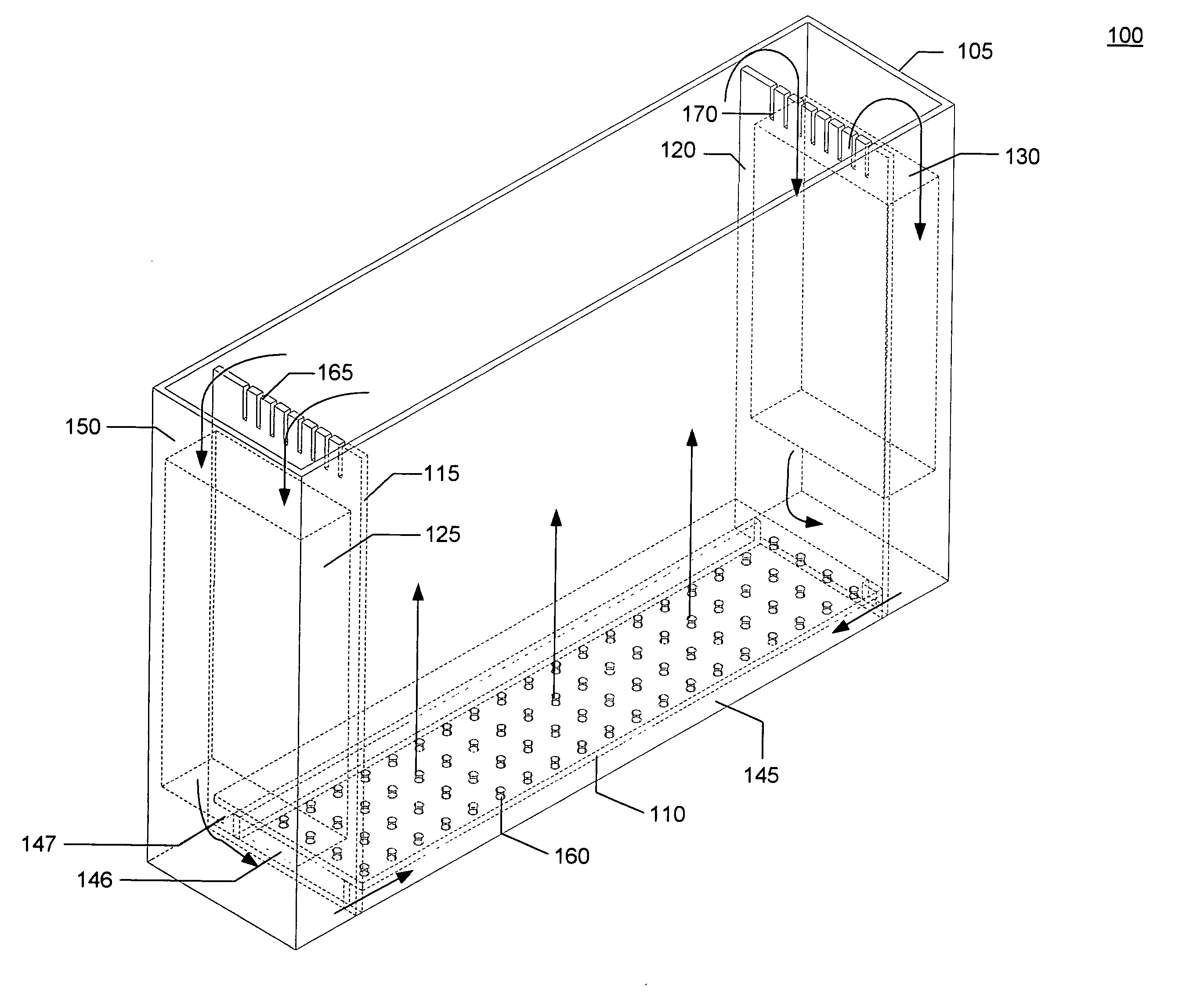
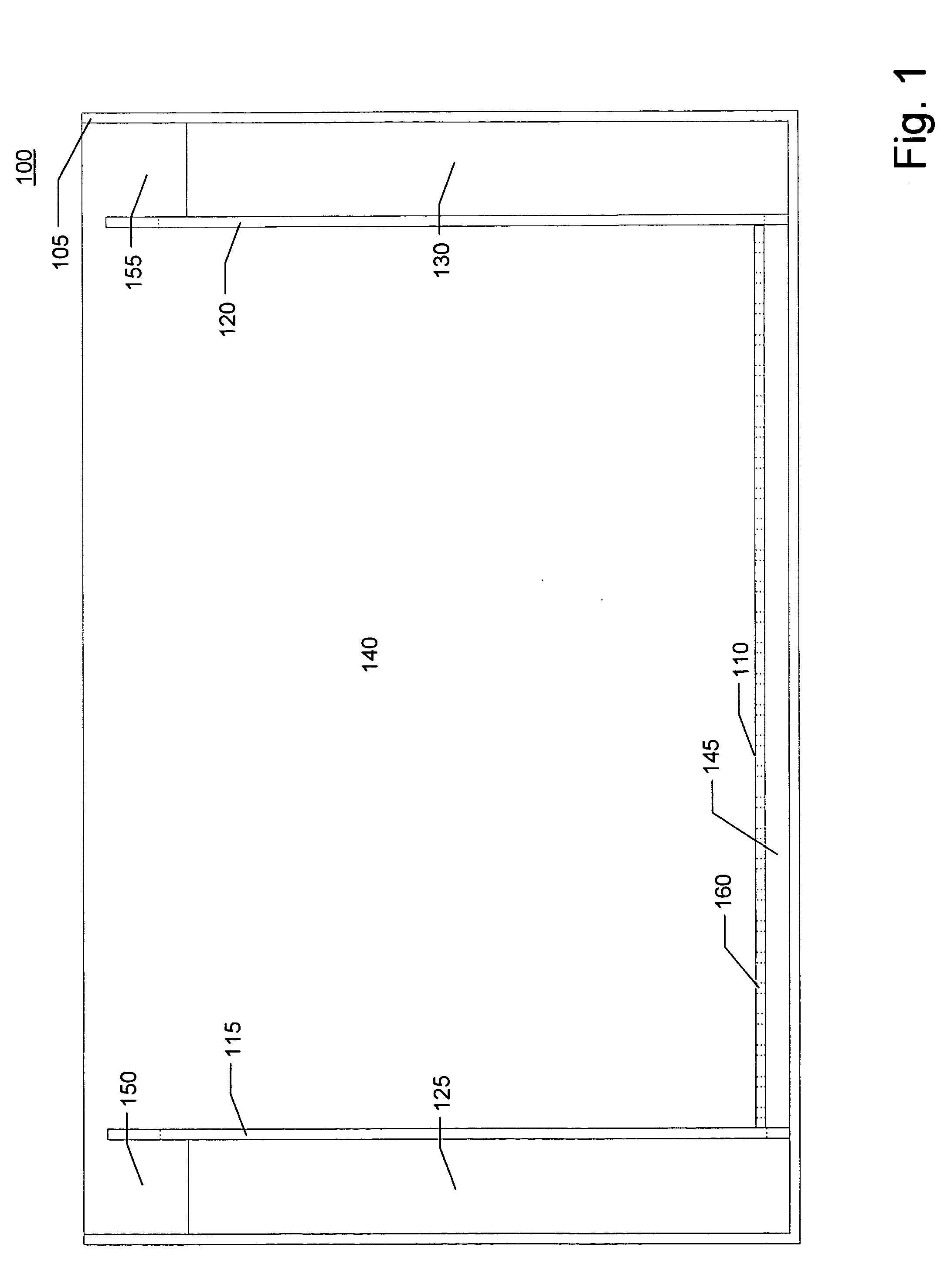
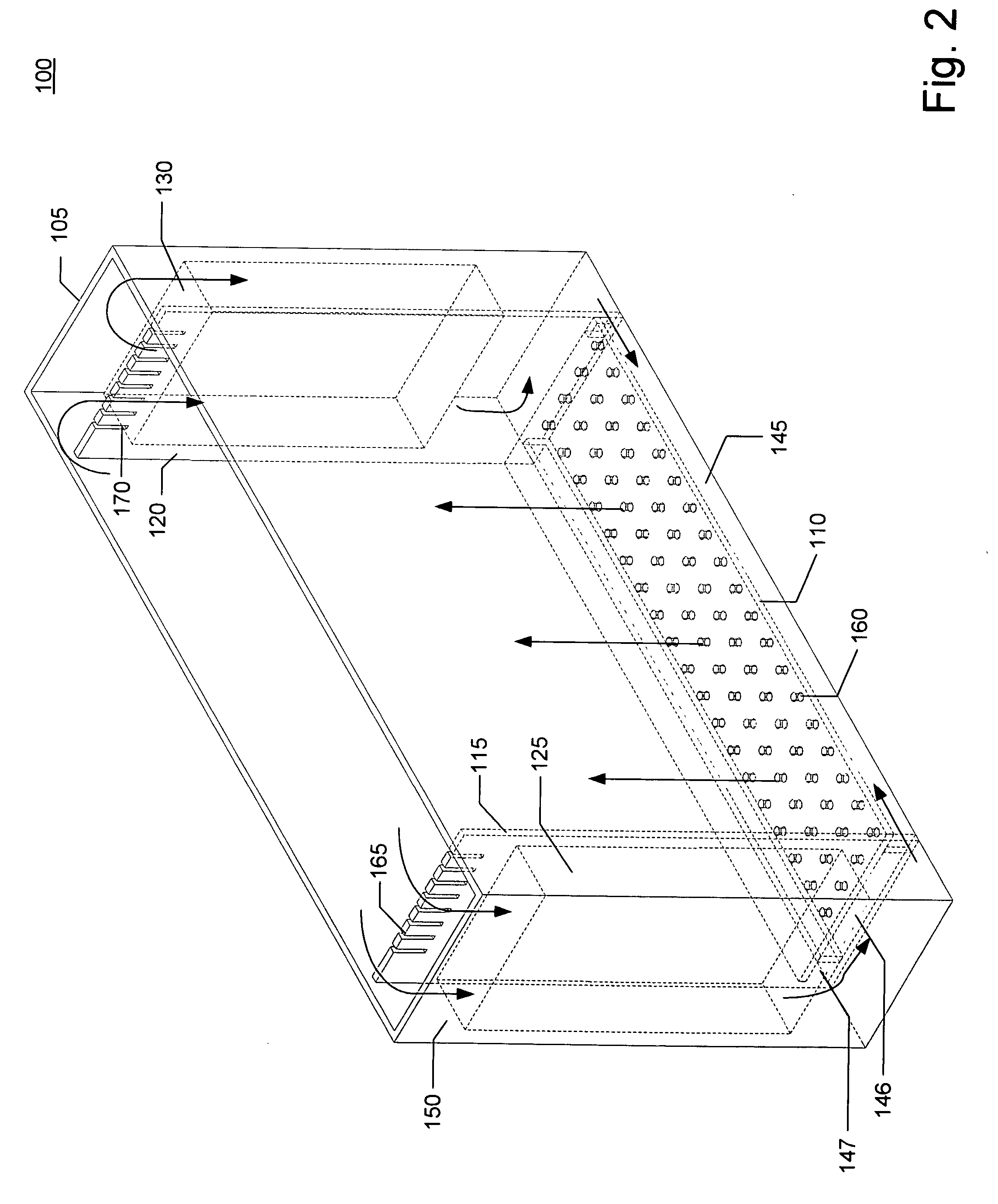
[0030] In conjunction with FIGS. 1 & 2, an exemplary embodiment of the present invention are depicted by an aquarium 100 comprising a container 105, a first plate 110, a second plate 115, a third plate 120, a filtration system 125 and a second filtration system 130. The first plate 110, second plate 115, third plate 120, filtration system 125 and second filtration system 130 are located within the container 105.

[0031] The container 105 has a height, a length and a depth and forms a main cavity 140, a lower cavity 145, a first side cavity 150 and a secon...


PUM


Abstract

The present invention provides a compact design and provides an improved viewable area. In an exemplary embodiment, the present invention comprises a container having a height, a depth and a width. The container comprises a main cavity, a lower cavity, at least one side cavity and a filtration system. The lower cavity is located below the main cavity and a first plate separates the lower cavity from the main cavity and allows limited fluid communication between the lower cavity and main cavity. The volume of the lower cavity is substantially less than the volume of the main cavity. The side cavity is located adjacent to the main cavity and a second plate separates the side cavity from the main cavity and allows limited fluid communication between the side cavity and main cavity. The side cavity has a volume less than the main cavity and more than the lower cavity.

Description

CROSS REFERENCE TO RELATED APPLICATIONS [0001] This application is related to, and incorporates by reference, U.S. patent application having Ser. No. ______, and entitled “AQUARIUM FILTER” which is filed concurrently herewith and is assigned to the same assignee.TECHNICAL FIELD [0002] The present invention relates to aquariums and, more particularly to an improved aquarium that requires a minimal amount of water while maximizing the livable area of the aquarium. BACKGROUND OF THE INVENTION [0003] Aquariums are a popular way to raise aquatic animals and plants for pets, as well as for aesthetic purposes. Aquariums are also used for business, scientific and educational purposes. However, such an aquarium generally occupies large spaces since there should be provided a filter device therein as well as about 10 and 20 gallons of water. Some larger aquariums require substantially more water. [0004] It is understood that aquarium water is changed to remove a build-up of chemicals, which t...

Claims


Application Information

Patent Timeline
IPC IPC(8): A01K63/04
CPCA01K63/003A01K63/045
Inventor HOCHGESANG, BRADLEY EARLHOCHGESANG, ANDREW KENT
Owner HOCHANG BRADLEY EARL
Why Eureka
Try Eureka