
Ecology fuel return systems

a fuel return system and ecology technology, applied in the direction of valve operating means/release devices, functional valve types, machines/engines, etc., can solve the problems of air leakage into the fuel system of the aircraft, the inability of traditional ecology fuel return systems to experience stability, and the localization of undesirable fuel-rich conditions in the combustor

Active Publication Date: 2016-01-28
HAMILTON SUNDSTRAND CORP
View PDF38 Cites 2 Cited by
  • Summary
  • Abstract
  • Description
  • Claims
  • Application Information

AI Technical Summary

Benefits of technology

This patent is related to a fuel return system for an engine that uses an ejector pump to recover fuel from a tank. The system includes a negative G control component that prevents fuel from flowing through the ejector pump during negative G events (when the vehicle is tilting or hitting uneven surfaces). This control is achieved through a negative G control component that includes a float and a negative G control mechanism. The negative G control mechanism can include a biasing component, such as a spring or a lever, that applies a force to the float to control its movement. Additionally, the system can include a slosh plate or a check valve to further damp the displacement of the float during negative G events. The technical effect of this system is to improve the stability and efficiency of the fuel return system during engine operation.

Problems solved by technology

Finally, ecology fuel return systems can drain the combustor of any unused fuel upon engine shut-down thus preventing any smoke exhaust from the engine upon engine start-up and potentially causing some localized undesirable fuel-rich conditions in the combustor (i.e., “hot spots”).
Traditional ecology fuel return systems can sometimes experience instability.
For example, there is a potential for air leakage into the aircraft's fuel system under some circumstances, such as negative G events that can occur during some flight maneuvers.
The air entrained in the fuel could interfere with normal operation of the engines.

Method used


Image

  • Ecology fuel return systems
  • Ecology fuel return systems
  • Ecology fuel return systems

Examples


Embodiment Construction

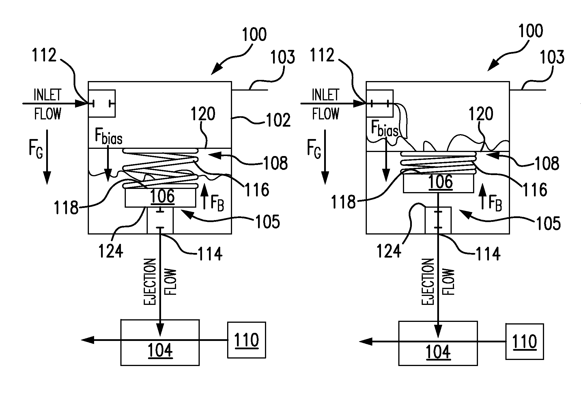
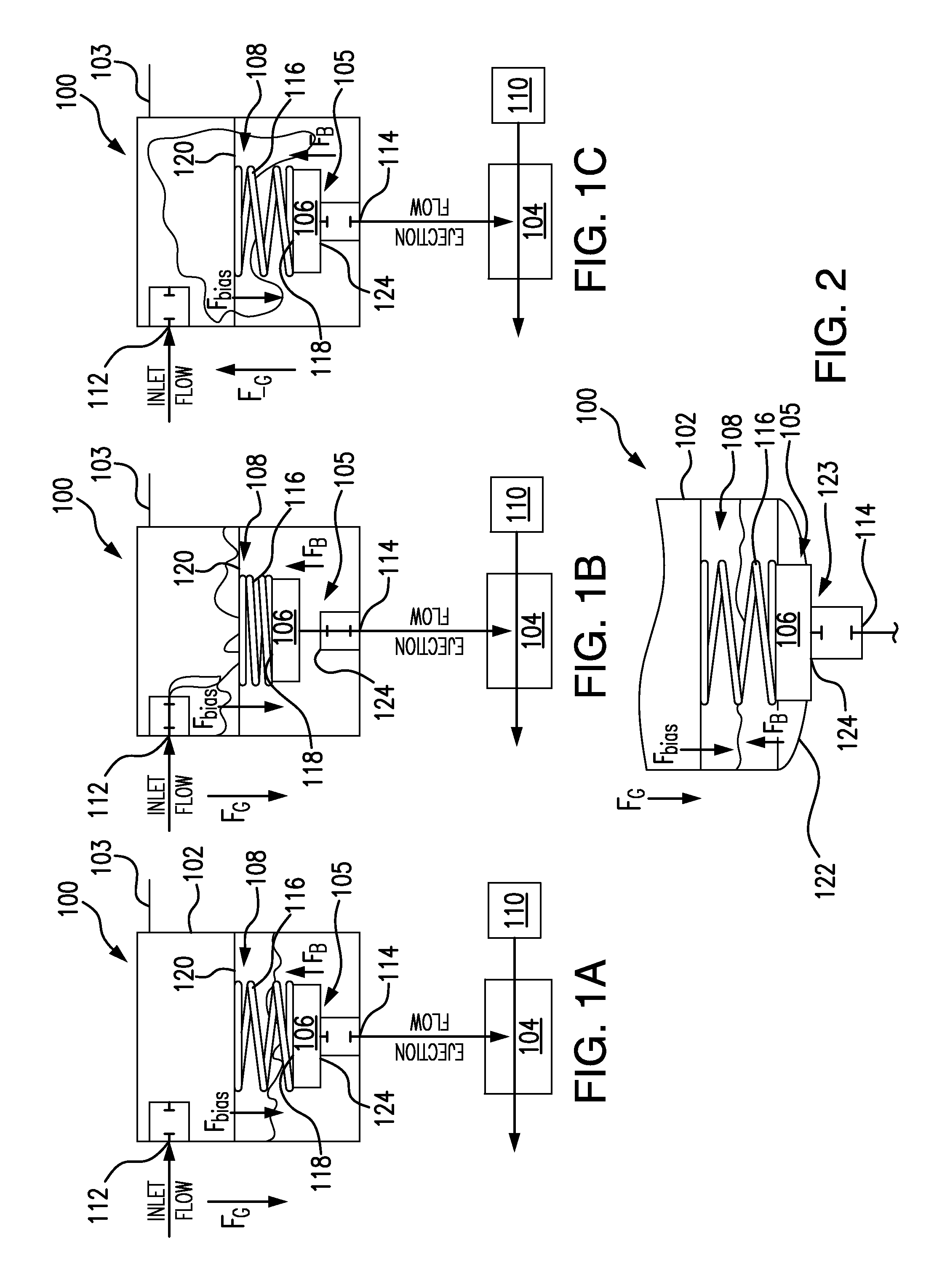
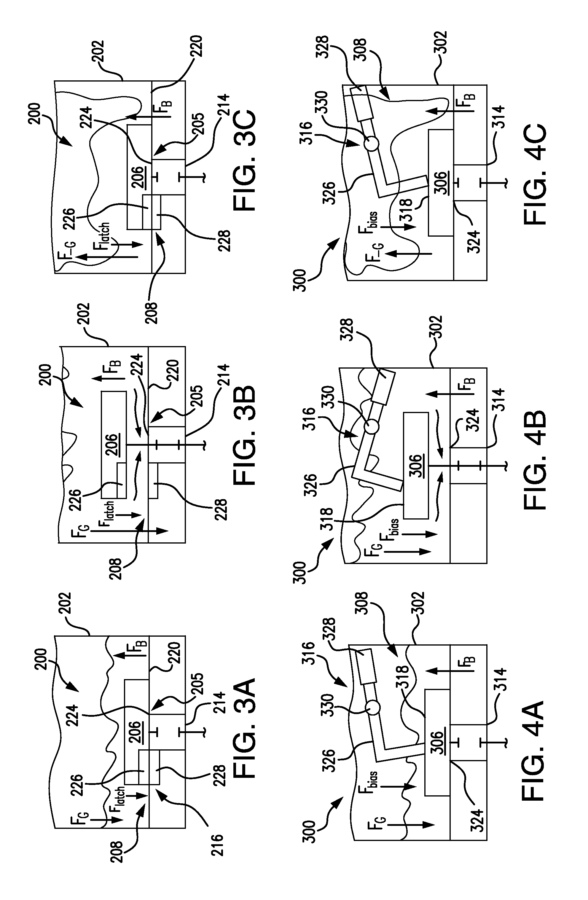
[0034]Reference will now be made to the drawings wherein like reference numerals identify similar structural features or aspects of the subject disclosure. For purposes of explanation and illustration, and not limitation, a perspective view of an exemplary embodiment of an ecology fuel return system in accordance with the disclosure is shown in FIG. 1A and is designated generally by reference character 100. Other embodiments of ecology fuel return systems in accordance with the disclosure, or aspects thereof, are provided in FIGS. 1B-7C, as will be described. The systems and methods of the invention can be used to reduce the entrainment of continuous airflow into the fuel system, for example during negative G loading events, such as during aircraft maneuvers and turbulence, where the tank is driven to accelerate against gravity.

[0035]As shown in FIG. 1A, an ecology fuel return system 100 includes a tank 102, an ejector pump 104, a boost pump 110, and a shut-off valve 105 with a floa...


PUM


Abstract

A shut-off valve includes a float and a negative G control component. The float is configured to occlude a tank outlet at a first fluid level and 1 G and unocclude the tank outlet at a second fluid level and 1 G. The negative G control component is operatively connected to the float to limit fluid, e.g. liquid or gas, communication between a tank outlet and an ejector pump during negative G events. An ecology fuel return system includes a tank, an ejector pump, a float, and a negative G control component, as described above. The tank has an inlet and an outlet. The inlet is configured to be in fluid communication with components of an engine. The ejector pump is in fluid communication with the tank outlet and is configured to pump fuel from the tank to a fuel pump inlet of an engine.

Description

BACKGROUND OF THE INVENTION[0001]1. Field of the Invention[0002]The present invention relates to fuel return systems, and, in particular, to valves in fuel return systems.[0003]2. Description of Related Art[0004]Traditional ecology fuel return systems can be found in gas turbine engines, for example, in gas turbine engines used in aircraft. A traditional ecology fuel return system is generally configured to remove a certain known amount of jet fuel from the engine's fuel manifolds, for example, fuel nozzle / injector manifolds, engine fuel supply lines, and the like, upon engine shutdown. Upon engine startup, the jet fuel from the ecology fuel return system is returned to the engine's fuel pump inlet via an ejector pump to be injected in the combustor thus providing stable engine idle operations. Ecology fuel return systems can minimize the amount of fuel left over in the engine's fuel system after engine shutdown, thus minimizing the possibility for any liquid fuel and / or any gaseous...

Claims


Application Information

Patent Timeline
Patent Type & Authority Applications(United States)
IPC IPC(8): F02C9/26F16K31/18
CPCF16K31/18F02C9/26F01D17/141F01D17/145F02C7/232F02C9/263F05D2300/507Y10T137/0826Y10T137/0898Y10T137/7323Y10T137/7436Y10T137/7442F05D2220/323F05D2260/601F16K31/22
Inventor CARPENTER, RICHARD J.GIBBONS, KEVINREUTER, CHARLES E.RIBAROV, LUBOMIR A.VEILLEUX, JR., LEO J.FLOW, ETHAN
Owner HAMILTON SUNDSTRAND CORP
Learn More