
Support surface system providing simultaneous alternating pressure and low air loss therapies

a technology of support surface and low air loss, which is applied in the field of therapeutic support surface, can solve the problems of pressure sores, tissue death, and skin tissue breakdown of patients, and achieve the effects of reducing the risk of recurrence, and improving the quality of li

Active Publication Date: 2016-06-14
ANODYNE MEDICAL DEVICE
View PDF28 Cites 3 Cited by
  • Summary
  • Abstract
  • Description
  • Claims
  • Application Information

AI Technical Summary

Benefits of technology

The patent describes a support surface system that provides low air loss therapy by using an upper chamber with an air channel and a valve to control fluid communication between the chambers. The system also includes an insert made of open cell foam to prevent the restriction of air flow and a spacer to prevent the upper surface from contacting the partition. Alternating pressure therapy can also be provided by the system. The technical effects of this system include improved airflow, reduced air loss, and improved pressure distribution for patients.

Problems solved by technology

Whenever a patient lays in bed for a prolonged period of time, especially for decreased mobility patients who stay mostly in the same position, the skin tissue of the patient can begin to breakdown.
As a result, the tissue is deprived of oxygen and nutrients, which, in turn, can cause the tissue to begin to die and can cause pressure sores to develop.
However, one problem with current designs of providing low air loss therapy in a top cover is the uneven distribution of air around the patient.
As a result, in some cases, little if any air reaches the upper torso of the patient due to air flow constrictions and / or drag.
However, this is not the case for foam mattresses that utilize air cylinders which are filled with foam.

Method used


Image

  • Support surface system providing simultaneous alternating pressure and low air loss therapies
  • Support surface system providing simultaneous alternating pressure and low air loss therapies
  • Support surface system providing simultaneous alternating pressure and low air loss therapies

Examples


Embodiment Construction

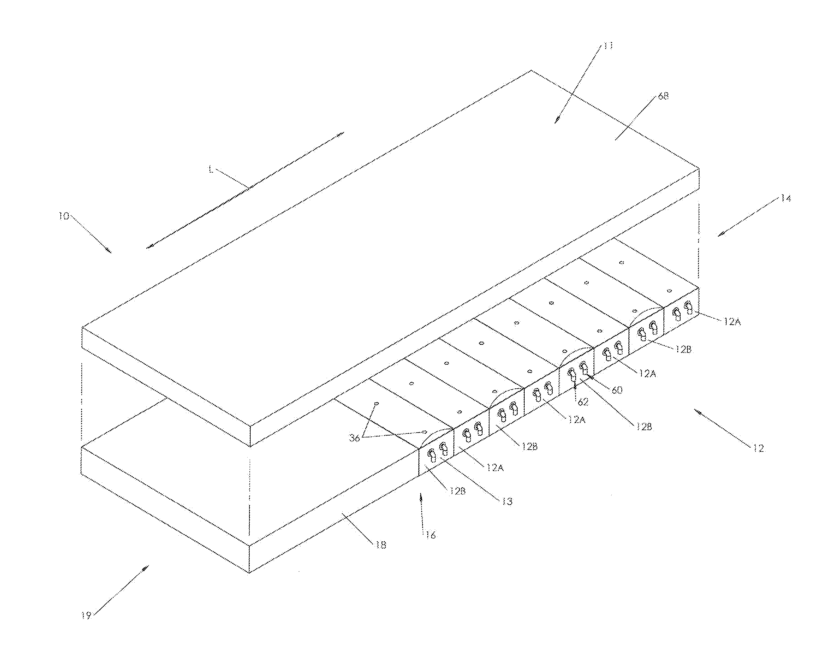
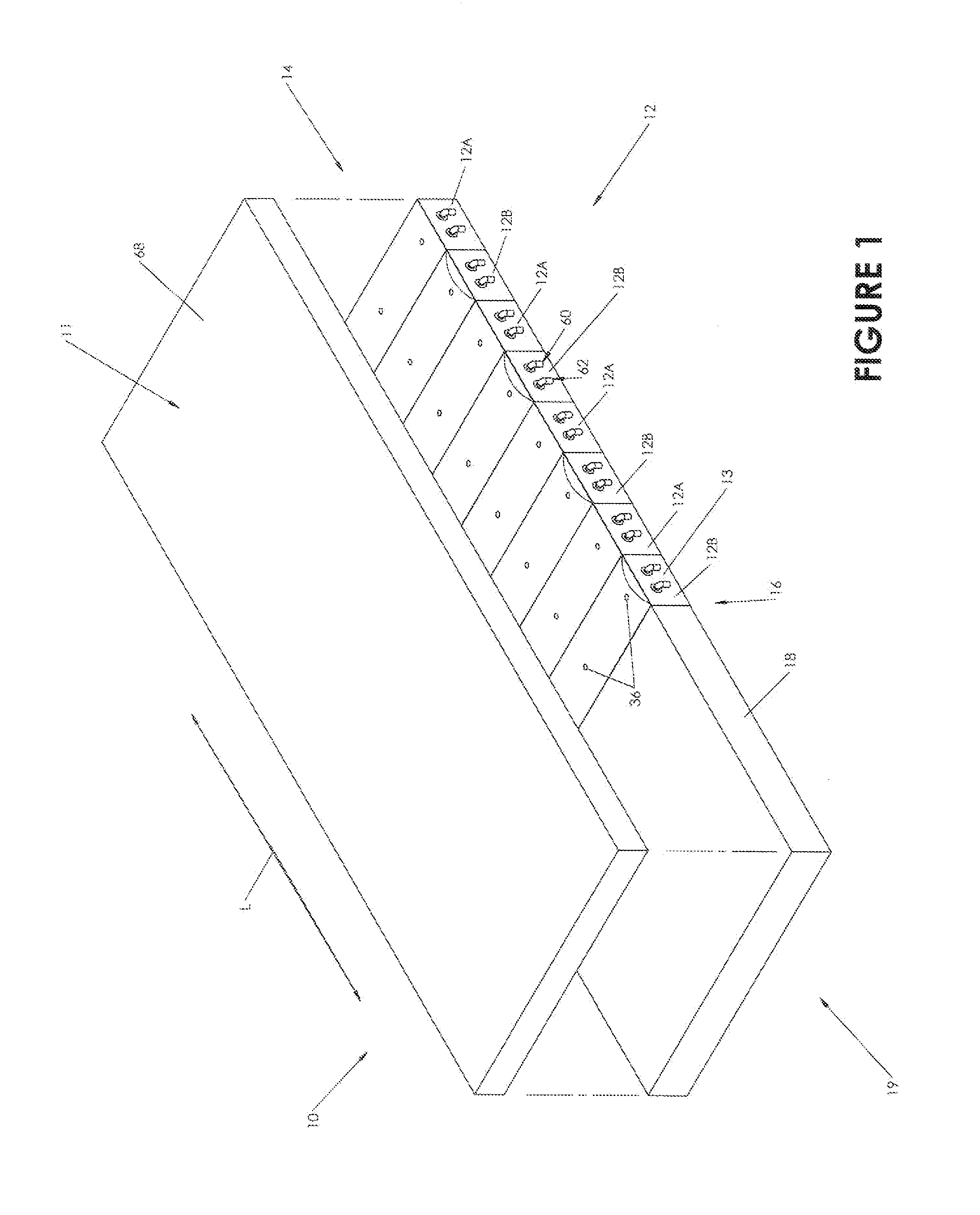
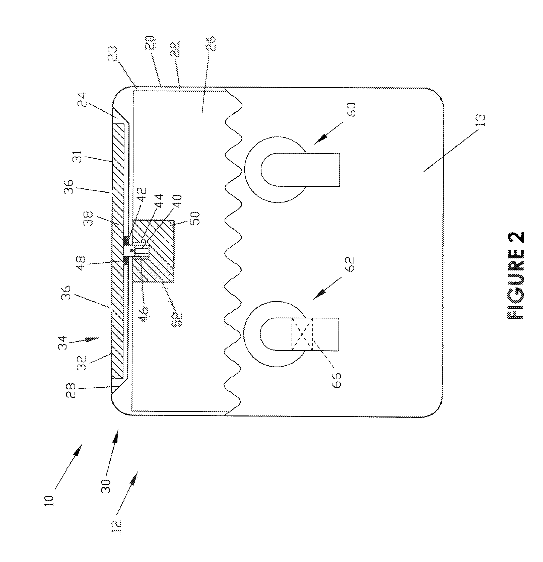
[0033]Embodiments are directed to a support system and an associated manner of operating the support system. Aspects will be explained in connection with one possible system, but the detailed description is intended only as exemplary. Embodiments are shown in FIGS. 1-5, but the embodiments are not limited to the illustrated structure or application. It will be appreciated that for simplicity and clarity of illustration, where appropriate, reference numerals have been repeated among the different figures to indicate corresponding or analogous elements. In addition, numerous specific details are set forth in order to provide a thorough understanding of the embodiments described herein. However, it will be understood by those of ordinary skill in the art that the embodiments described herein can be practiced without these specific details.

[0034]Embodiments are directed to a support surface system 10 that can simultaneously provide alternating pressure therapy and low air low therapy to...


PUM


Abstract

A support surface system provides alternating pressure therapy and low air loss therapy simultaneously using a single pump. The system includes a plurality of cells. Each cell has a foam-filled lower chamber and an upper chamber. Fluid communication between the lower and upper chambers is controlled by a normally closed valve that opens if the pressure within the lower chamber exceeds a predetermined threshold pressure. Pressurized air is alternatingly supplied to the lower chambers of a first subset of cells and the lower chambers of a second subset of cells, thereby providing alternating pressure therapy. When the pressure in the lower chamber exceeds the threshold, the valve opens to allow air from the lower chamber to flow into the upper chamber. Air is expelled from the upper chamber through perforations therein, to remove moisture and humidity and possibly reducing the temperature of the micro-climate beneath a patient.

Description

CROSS-REFERENCE TO RELATED APPLICATIONS[0001]The present application is a continuation of U.S. patent application Ser. No. 12 / 882,966, filed on Sep. 15, 2010, now U.S. Pat. No. 8,852,131, issued on Oct. 7, 2014, which is incorporated by reference herein in its entirety.FIELD[0002]Embodiments relate in general to support surfaces and, more particularly, to therapeutic support surfaces.BACKGROUND[0003]Whenever a patient lays in bed for a prolonged period of time, especially for decreased mobility patients who stay mostly in the same position, the skin tissue of the patient can begin to breakdown. Some of the most common factors that contribute to skin tissue breakdown are continuous pressure on any part of the body, friction or shear on the skin, prolonged moisture against the skin and elevated temperatures. For example, when a portion of the body is subjected to a continuous pressure, the blood supply to skin tissue can be cut off. As a result, the tissue is deprived of oxygen and nu...

Claims


Application Information

Patent Timeline
IPC IPC(8): A47C27/10A61G7/00A61H9/00A61G7/057A47C21/04
CPCA61G7/05776A61G7/05769A47C27/10A61H9/0078A61G7/05715A61G2007/05792A47C21/046A61G7/05792
Inventor SIEGNER, KENNETH SCOTT
Owner ANODYNE MEDICAL DEVICE
Learn More