Bicycle crank assembly

Inactive Publication Date: 2006-05-18
SCHLANGER RAPHAEL
View PDF10 Cites 33 Cited by
  • Summary
  • Abstract
  • Description
  • Claims
  • Application Information

AI Technical Summary

Benefits of technology

[0010] In accordance with the present invention, it has now been found that the forgoing objects and advantages may be readily obtained.
[0011] Bicycle racers and cycling enthusiasts are in a constant quest to increase the performance of their equipment by reducing its weight. This is well known in the field and is particularly applicable to the rotating components of the bicycle such as the crankset. It is an object of the present invention to provide a bicycle crank assembly that is light in weight, preferably lighter than traditional crank assemblies, while maintaining the requisite structural integrity. It is a further object of the present invention to produce a lightweight crank assembly that can be produced economically to minimize any additional expense associated with the increase in performance.
[0012] The present invention utilizes a crank axle that is constructed, at least in part, from fiber reinforced composite materials that are high in strength and light in weight. This type of material is highly advantageous in a crank axle application. In addition, it is preferable that the crank axle and at least one of the crank arms be molded as one contiguous unit.

Problems solved by technology

However, these crank assemblies still utilize crank axles made of steel, which is a very high-density material, and results in a crank axle that is quite heavy.
Such a connection may be considered a structural interruption of the crank axle and this type of design places this connection at a very highly stressed region of the crank axle, which may result in a weaker and / or heavier connection.
Additionally, this region also has severe geometric constraints due to the surrounding bottom bracket shell (not shown) of the bicycle frame.
Further, since the region of connection is completely enclosed by the bottom bracket shell and the bearings, access and means to operate the connection are severely limited.
This results in further constraints on the design of this connection and further limits the ability to create a rigid, strong and lightweight connection.
Needless to say, such designs have had only limited success in the marketplace.
In addition, the connection between the crank arm(s) is somewhat complex and requires the expense of precision machining and additional manufacturing steps to achieve a reliable connection.
Further, this connection requires additional components, such as fixing bolt(s), which add cost and weight to the overall assembly.

Method used


Image

  • Bicycle crank assembly
  • Bicycle crank assembly
  • Bicycle crank assembly

Examples


Embodiment Construction

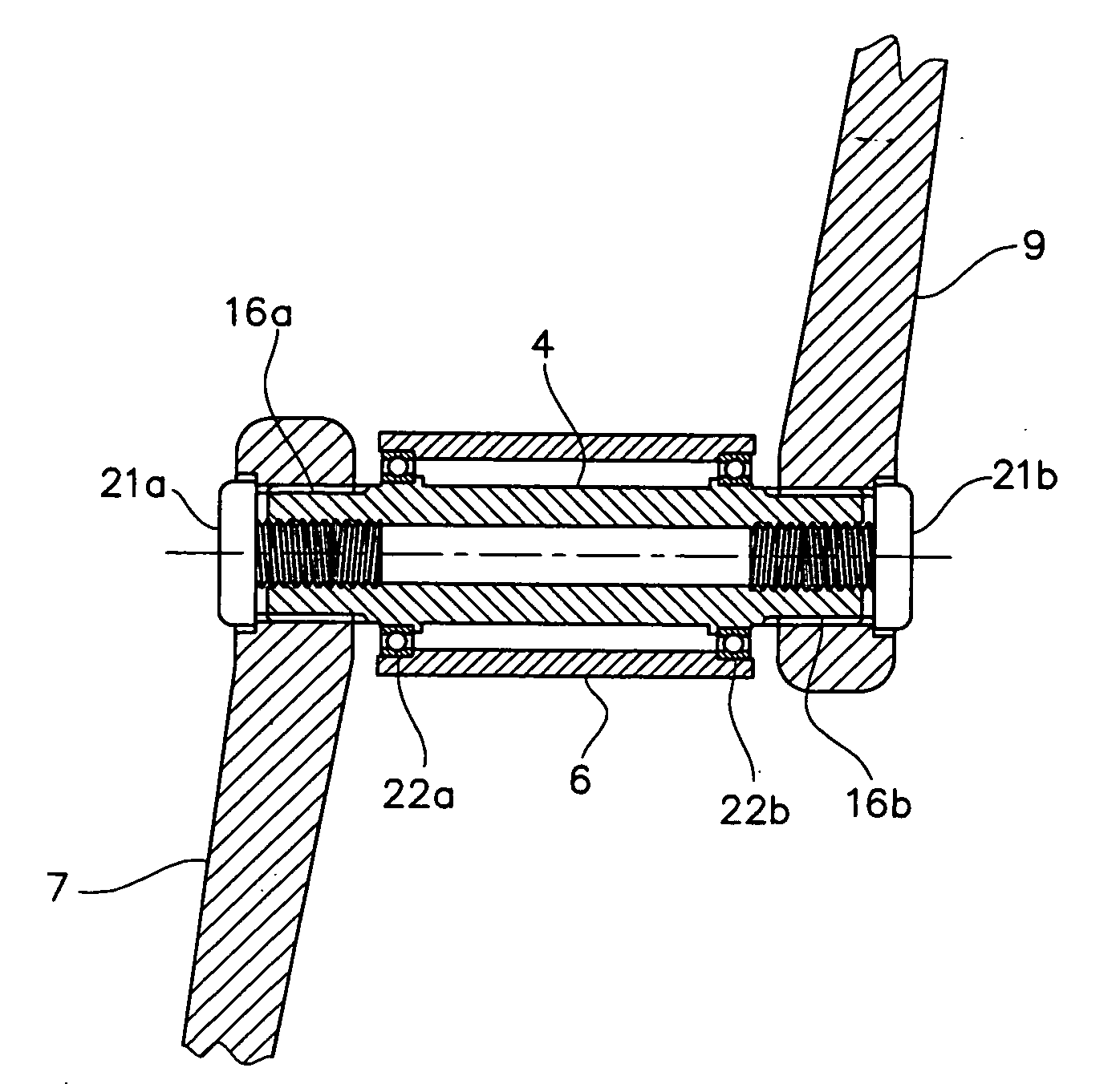
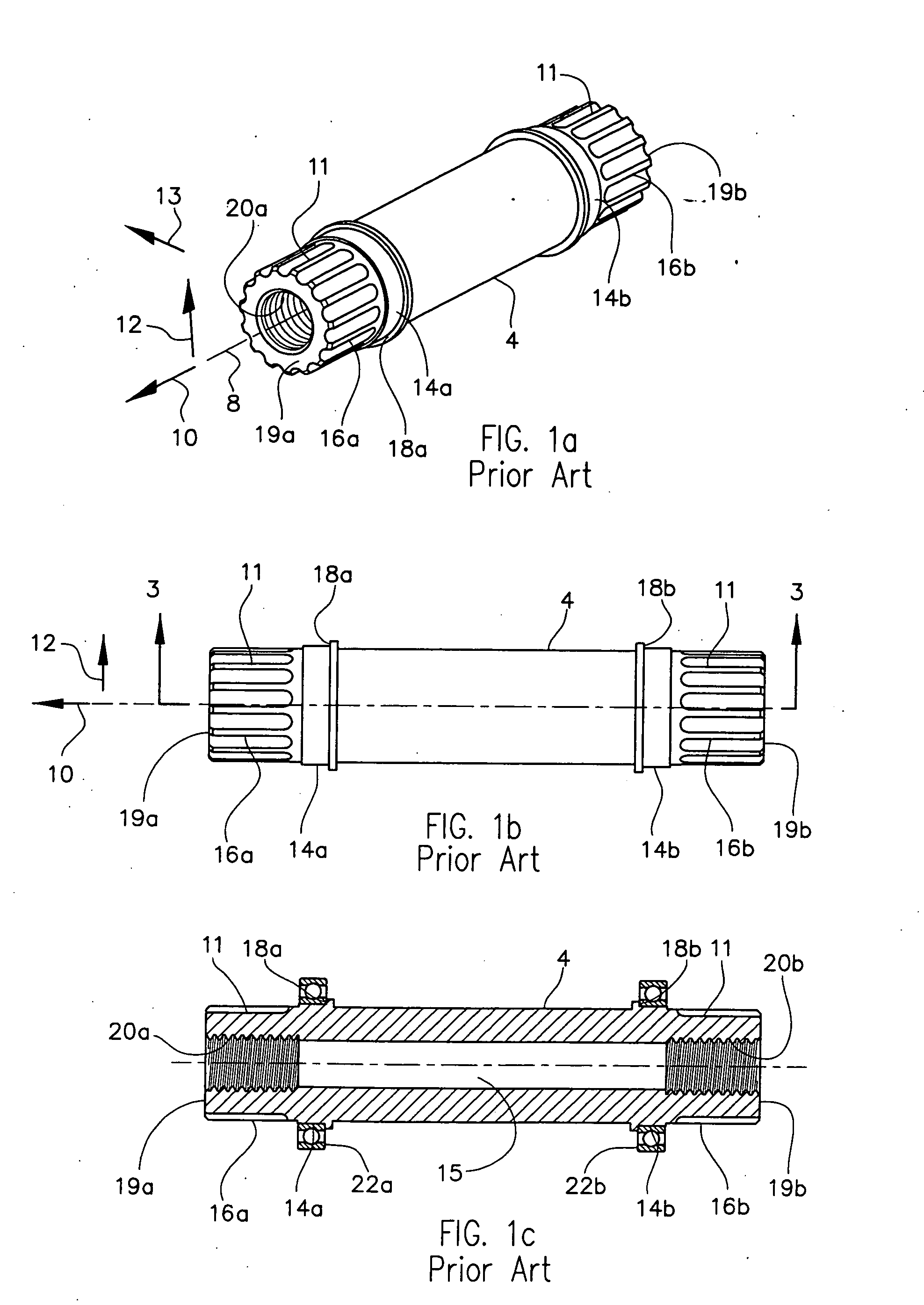
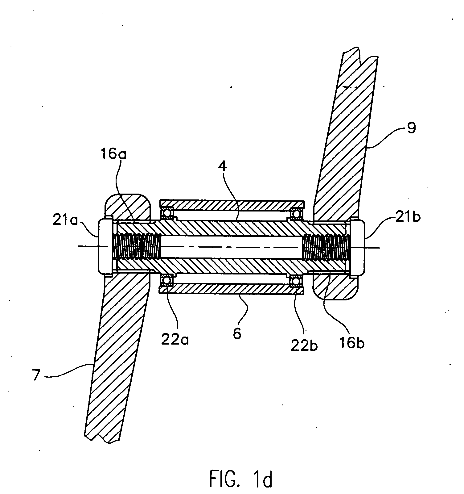
[0049]FIGS. 1a-c describe a prior art crank axle 4. For the sake of orientation convention, the crank axle 4 may be considered as a generally cylindrical component that has a longitudinal or axial axis 8 about which it rotates. The axial direction 10 is a direction parallel to the axial axis 8. The radial direction 12 is a direction extending radially and perpendicular to the axial axis 8. The tangential direction 13 is a direction tangential about the axial axis 8 at a radial distance from the axial axis 8. The term “axially inboard” refers to an axial location proximal to a point on the axial axis 8 that is generally midway between bearing surfaces 14a and 14b. Conversely, the term “axially outboard” refers to an orientation that is distal from this point. Similarly, “radially inboard” refers to an orientation proximal to the axial axis 8 and “radially outboard” refers to an orientation distal to the axial axis 8.

[0050] Crank axle 4 has relatively conventional geometry and includ...


PUM


Abstract

An improved bicycle crankshaft assembly, including a crank axle with an axial axle axis, a first axle end, and a second axle end axially opposed to the first axle end; a first crank arm connected to the crank axle at a first crank arm interface adjacent the first axle end; a second crank arm connected to the crank axle at a second crank arm interface axially spaced from the first crank arm interface; a first bearing surrounding said crank axle adjacent said first axle end for rotation of said crank axle about said axial axis; a second bearing surrounding the crank axle and axially spaced from the first bearing. The crank axle includes reinforcement fibers for structural reinforcement of the crank axle and the crank axle is an integral crank axle that simultaneously contacts both the first bearing and the second bearing.

Description

CROSS-REFERENCE TO RELATED APPLICATION [0001] This application claims priority of U.S. provisional patent application 60 / 628,773, filed Nov. 17, 2004, and entitled “Crank Axle Assembly”.BACKGROUND OF THE INVENTION [0002] (1) Field of the Invention [0003] This invention is related to the crank axle of a bicycle crank assembly and is particularly related to a crank axle of fiber-reinforced construction and to the connection between a fiber-reinforced crank axle and a crank arm. [0004] (2) Description of the Related Art [0005] A bicycle crank assembly or crankset has traditionally been designed as a 3-piece assembly consisting of a crank axle, a left crank arm, and a right crank arm. The left crank arm is connected to the left end of the crank axle via a system of straight and / or tapered splines in combination with a fixing bolt to secure the connection. Likewise, the right crank arm is connected to the right end of the crank axle in a similar arrangement. The crank axle is radially su...

Claims


Application Information

Patent Timeline
IPC IPC(8): B62M1/02B62M1/36
CPCB62M3/00Y10T74/2164B62M3/003
Inventor SCHLANGER, RAPHAEL
Owner SCHLANGER RAPHAEL
Why Eureka
Try Eureka