Service case

Inactive Publication Date: 2005-05-10
HILL PHOENIX
View PDF34 Cites 20 Cited by
  • Summary
  • Abstract
  • Description
  • Claims
  • Application Information

AI Technical Summary

Benefits of technology

[0011]In accordance with the present invention, the f

Problems solved by technology

However, although these methods hide the coil, they do not make the case particularly attractive and may affect refrigeration efficiency.
Therefore, in both of the foregoing applications, the actual cooling of the product is achieved from the gravity feed coil mounted above the shelf or from the forced air coil mounted below the shelf, which is not entirely satisfactory.

Method used


Image

  • Service case
  • Service case

Examples


Embodiment Construction

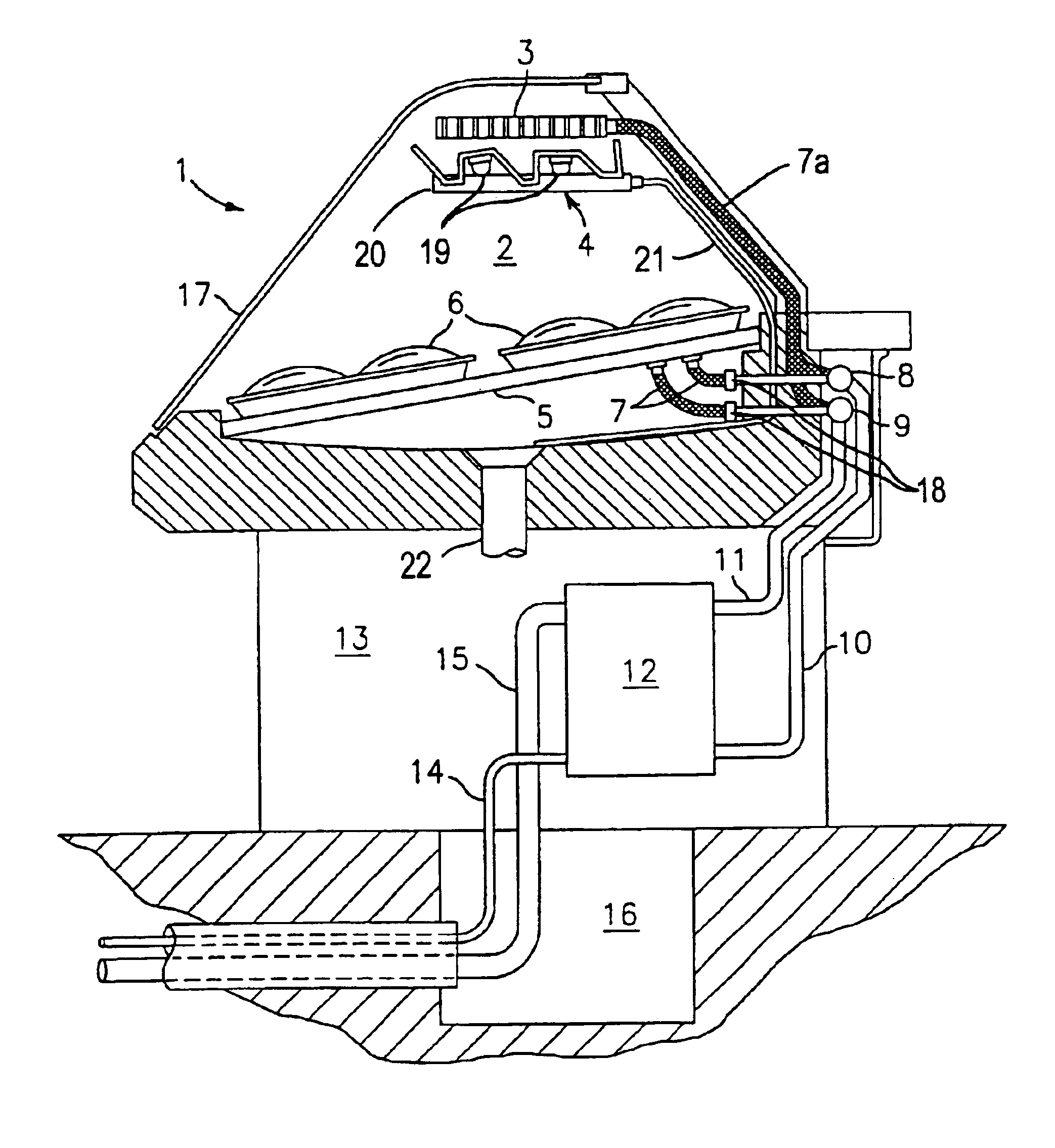
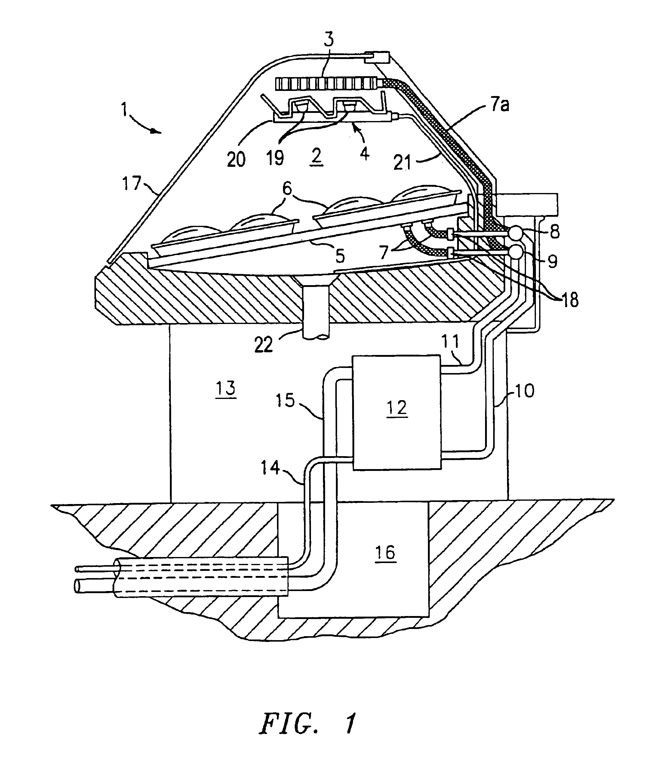
[0016]FIG. 1 shows a cross-section of the secondary coolant service gravity case (1). The secondary coolant gravity coil (3) is situated near the top of the refrigerated space (2). Mounted below the coil is a gravity louver assembly (4) which is designed to both direct air flow through the refrigerated spice and catch water falling from the coil above from condensation or melted during defrost cycles. A drain pan (20) directs the flow of water from the louvers into piping (21) connected to the main case drain (22). The louver assembly may also contain an integrated lighting system (19) to better illuminate the product.

[0017]Secondary coolant is also circulated through channels inside refrigerated pans (5) which provide additional cooling. The pans may be insulated on their underside to prevent heat transfer to the unused space below. Above the pans, the products (6) are placed in containers made of a metallic or otherwise heat-conductive material. The secondary coolant flows to and ...


PUM


Abstract

A temperature controlled service case for storage and display of chilled or frozen products, including at least one compartment for product storage, at least one access opening providing entrance to the compartment, at least one shelf within the compartment for holding product, and refrigeration operatively associated with the compartment for maintaining a selected temperature therein. The refrigeration includes at least one cooling coil above the shelf with a cooling medium flowing therethrough, and cooling within the shelf with a cooling medium flowing therethrough. Coolant supply is also provided for supplying cooling medium to the cooling coil and shelf.

Description

CROSS-REFERENCE TO RELATED APPLICATION[0001]This application claims the benefit of U.S. Provisional Application Ser. No. 60 / 314,196, filed Aug. 22, 2001.BACKGROUND OF THE INVENTION[0002]The present invention relates to a temperature controlled case for storage and display of chilled and / or frozen products, especially in a store environment.[0003]A typical cooling coil in a refrigerated case is constructed of metal, such as copper or aluminum. Since this material is metal, it is quite noticeable when mounted in a refrigerated case. Case manufacturers try to conceal this coil by placing an attractive cover over the coil or placing the coil in a hidden location, as under the product shelf. However, although these methods hide the coil, they do not make the case particularly attractive and may affect refrigeration efficiency.[0004]Refrigeration case shelving is generally made from painted metal or stainless steel. This type of shelving may be used to cover a forced air evaporator mounte...

Claims


Application Information

Patent Timeline
IPC IPC(8): A47F3/04
CPCA47F3/0491A47F3/0456
Inventor LANE, MARKDAVIDSON, MICHAEL B.ARSHANSKY, YAKOVHINDE, DAVID K.WALKER, RICHARD N.
Owner HILL PHOENIX
Why Eureka
Try Eureka