Calibration techniques for simplified high-frequency multiport differential measurements

a multi-port differential measurement and calibration technique technology, applied in the direction of resistance/reactance/impedence, instruments, measurement devices, etc., can solve the problems of prohibitively expensive, system can also have similar insertion loss problems, and the process of maintaining accuracy becomes more difficul

Active Publication Date: 2006-05-18
ANRITSU CORP
View PDF9 Cites 20 Cited by
  • Summary
  • Abstract
  • Description
  • Claims
  • Application Information

AI Technical Summary

Problems solved by technology

However, as multiport measurements are attempted at higher frequencies on these devices, the process of maintaining accuracy

Method used


Image

  • Calibration techniques for simplified high-frequency multiport differential measurements
  • Calibration techniques for simplified high-frequency multiport differential measurements
  • Calibration techniques for simplified high-frequency multiport differential measurements

Examples


Embodiment Construction

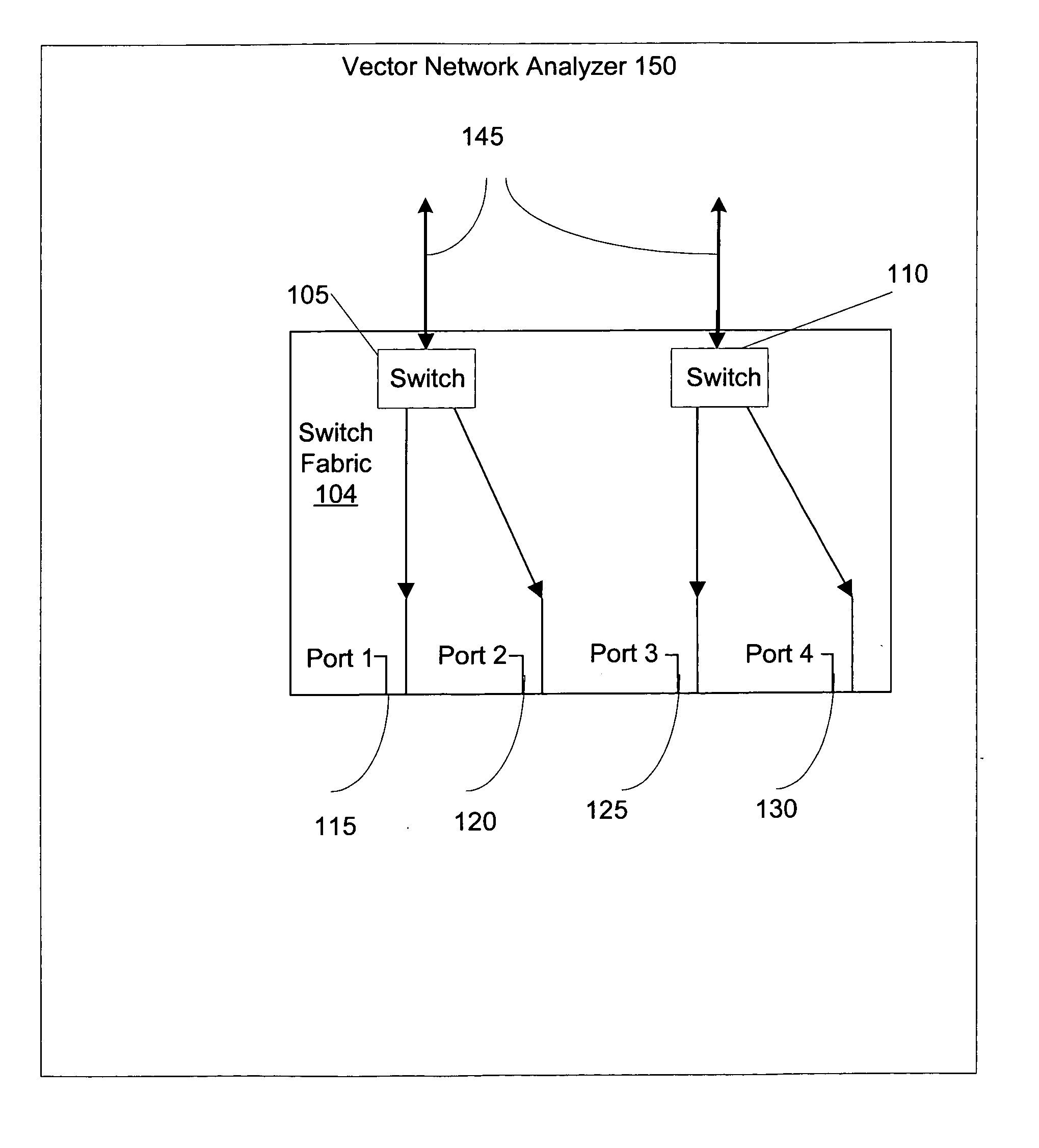
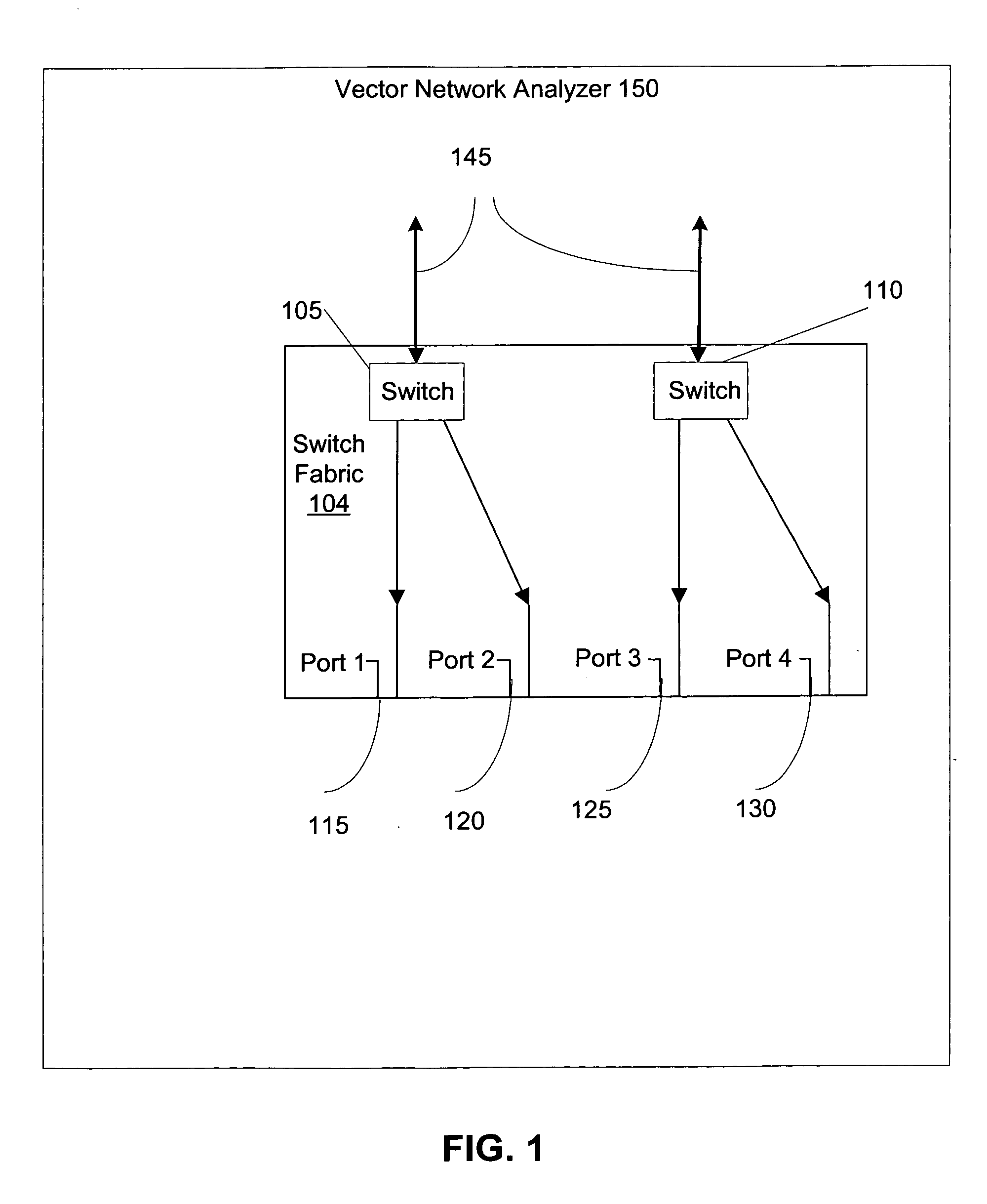
[0010] Embodiments of the present invention are directed towards systems, methods, and computer readable media for performing multiport vector network analysis. Embodiments of the present invention relate to a multiport network analysis calibration technique that is derived from a family of two port calibration techniques including Thru / Reflect / Line(TRL), Thru / Reflect / Match(TRM), Line / Reflect / Line (LRL), Line / Reflect / Match (LRM) and others. An improved calibration method enables a simplified switch matrix to perform accurate vector network analysis in communications and networking systems. After determining some characteristics through conventional methods, a two tier load match correction is performed on the results. The improved correction mechanism enables the system to perform comparably to systems with more complicated switch matrices.

[0011]FIG. 1 illustrates a switch fabric for a vector network analyzer in accordance with one embodiment of the present invention. The vector ne...


PUM


Abstract

Embodiments of the present invention are directed towards systems, methods, and computer readable media for performing multiport vector network analysis. Embodiments of the present invention relate to a multiport network analysis that is derived from a family of two port calibration techniques including Thru/Reflect/Line(TRL), Thru/Reflect/Match(TRM), Line/Reflect/Line (LRL), Line/Reflect/Match (LRM) and several others. An improved calibration method enables the use of a simplified switch matrix to perform accurate vector network analysis in communications and networking systems. After determining some characteristics through conventional methods, a two tier load match correction is performed on the results. The improved correction mechanism enables the system to perform comparably to systems with more complicated switch matrices.

Description

FIELD OF THE INVENTION [0001] The present invention deals generally with improved techniques for performing multiport vector network analysis. The present invention relates more specifically to an improved method for calibrating such methods. BACKGROUND OF THE INVENTION [0002] Multiport and differential Vector Network Analyzer (VNA) measurements are used in a wide variety of communications applications. The purpose of a vector network analyzer is to measure the magnitude and phase of the reflection and transmission characteristics of a microwave component as functions of frequency. A component can be inserted between the test ports, the test signal is rapidly tuned over a span of frequency, and portions of this signal are reflected from and transmitted through the component. These measurements are critical for accurately analyzing the characteristics of equipment such as telecommunications and data components, gigabit Ethernet backplanes, and other devices. However, as multiport mea...

Claims


Application Information

Patent Timeline
IPC IPC(8): G01R35/00
CPCG01R27/28G01R35/005
Inventor MARTENS, JONJUDGE, DAVIDBIGELOW, JIMMY
Owner ANRITSU CORP
Why Eureka
Try Eureka