High-accuracy low-power current sensor with large dynamic range

a low-power current sensor, high-accuracy technology, applied in the direction of pulse generators, instruments, pulse techniques, etc., can solve the problems of not being able to automatically compensate errors, not being able to measure the flow of electricity accurately over a wide dynamic range, and the physical size of the sense resistor b>2/b> can thus get to be a problem

Active Publication Date: 2012-04-12
SENSATA TECHNOLOGIES INC
View PDF3 Cites 22 Cited by
  • Summary
  • Abstract
  • Description
  • Claims
  • Application Information

AI Technical Summary

Problems solved by technology

It is not easy to measure the flow of electricity accurately over a wide dynamic range while dissipating very little waste heat.
It is not uncommon for a DC-supplied system to spend most of its time operating at a very low power level, and to consumes the full-rated energy only for relatively brief intervals.
But any non-identical temperature distributions as between the two paths can give rise to errors which are not automatically compensated by the use of differential sensing.
The physical size of the sense resistor 2 can thus get to be a problem, as can be the need to providing adequate cooling of the sense resistor.
The voltage signal in the Hall-effect device is linearly proportional to both the supply current and the magnetic field, within limitations of power dissipation resulting from the supply current, and some additional anomalous effects.
This means that there is always some latency between a current event of interest and the detection of such an event after the averaging or filtering has taken place.
A further potential difficulty with such magnetically coupled measurements (particularly where a DC current is converted to AC for purposes of Hall-effect sensing) is that during the zero crossings of the excitation voltage (that is, near the zero values for the sine-wave excitation), the Hall-effect device is altogether insensitive to the magnetic field, and simply discards any information for the duration of the zero-crossing transitions.
These factors make the Hall effect sensing less than ideal, particularly for a battery-powered system.
For the MR-effect approaches, the notably worst performance is in respect to the zero-current offset for the MR-effect based measurements.

Method used


Image

  • High-accuracy low-power current sensor with large dynamic range
  • High-accuracy low-power current sensor with large dynamic range
  • High-accuracy low-power current sensor with large dynamic range

Examples


Embodiment Construction

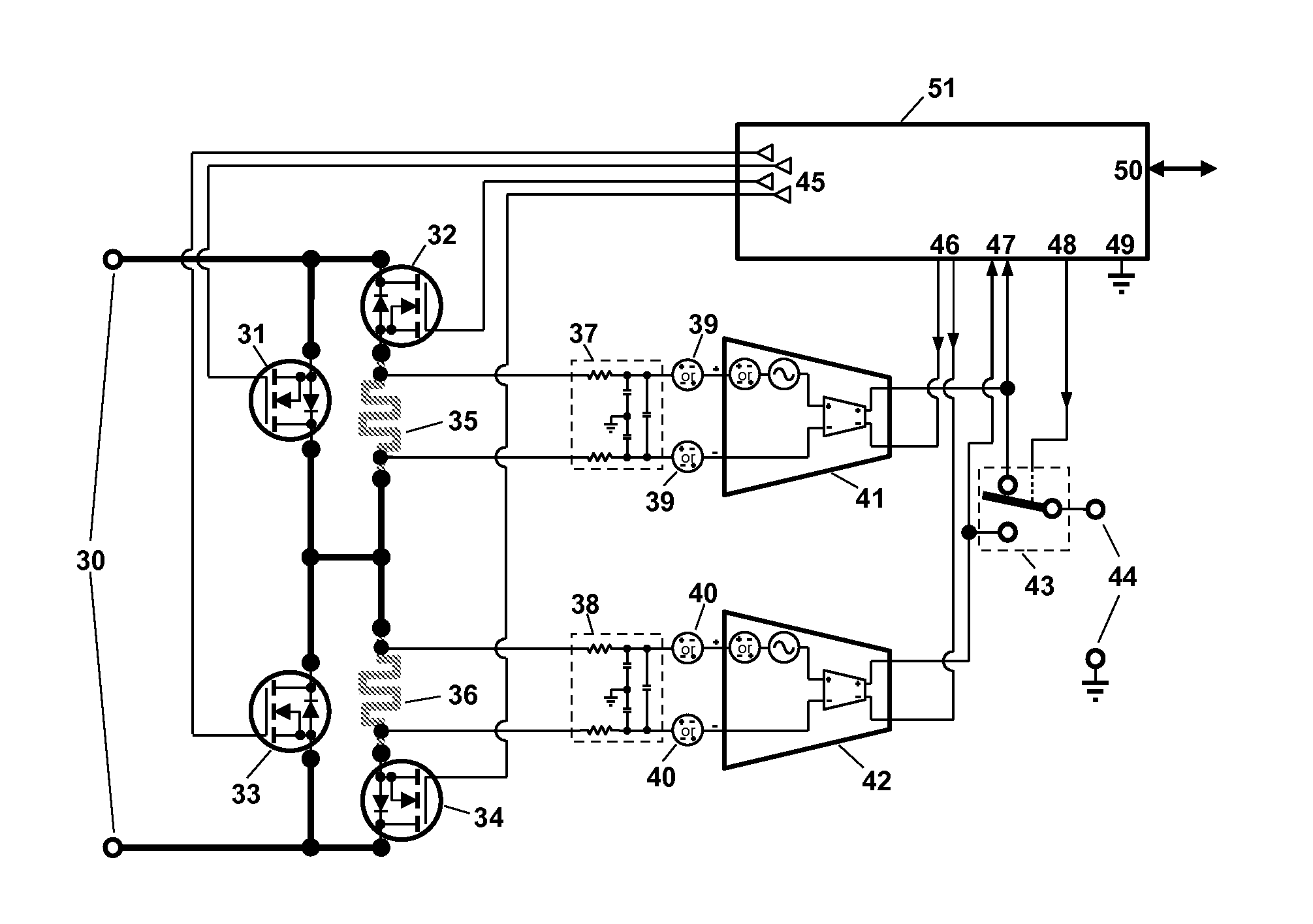
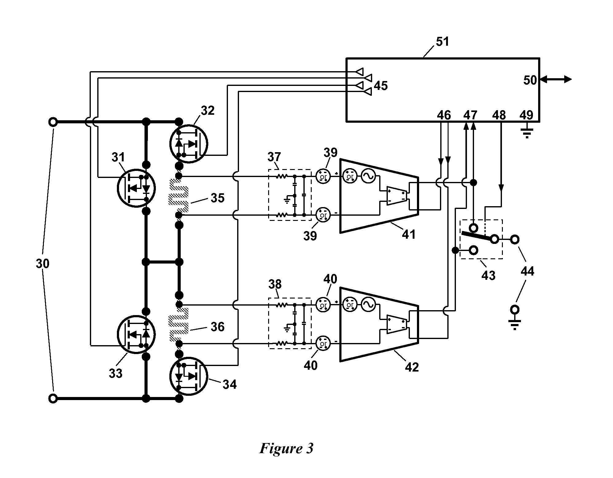
[0055]One embodiment of the invention is shown in FIG. 3. There are two identical current shunts 35 and 36, encircled by power field-effect transistors (FETs) 31-34. Current sense signals pass via RFI filters 37 and 38, and then amplified by IA 41 and 42. An analog selector switch 43 delivers the signal to Output Terminals 44; this signal can be either the output from IA 41, or TA 42. The system presents itself to the outside world at load current terminals 30.

[0056]Under control of the control circuit 51, and via FET Drivers 45, the FETs 31-34 are turned either fully on or off, as required for the execution of the algorithm detailed in FIG. 4.

[0057]The action of FETs 31-34 can direct the current through the current shunts 35, 36, or can disconnect either of shunts 35, 36 by breaking the circuit (by means of FET 32 or 34) and by bypassing the current around each shunt (by means of FET 31 or 33).

[0058]As will be discussed below, the system is controlled in such a way that at any mome...


PUM


Abstract

A current sensing approach makes use of two shunts in series, embedded in a switching fabric, each shunt the object of a differential measurement of voltage drop across the shunt. Methodical make-before-break cycling of the switches in the switching fabric permit real-time or very near-real-time measurement of nearly all of the errors such as offset errors present in each differential-measurement path. Additional differential measurement paths can be connected with the shunts, with RFI filtering at shorter time constants to serve electronic fuse needs.

Description

CROSS-REFERENCE TO RELATED APPLICATIONS[0001]This application claims the benefit of U.S. patent application No. 61 / 385,102 filed Sep. 21, 2010, which application is incorporated herein by reference.BACKGROUND[0002]It is not easy to measure the flow of electricity accurately over a wide dynamic range while dissipating very little waste heat.[0003]Whenever electrical energy is used, it is desirable to measure the quantity of energy used, both per unit of time (e.g. power), and over a specific amount of time (for example, energy used per month). In a residential environment, an electric power meter is a familiar fixture; it allows the power-providing companies to charge their customers for the energy used.[0004]In the most basic terms, the instantaneous power is a product of the voltage applied to, and the current flowing through, the load. An integration of this product (power) over a specific time interval yields the total consumption of the electrical energy within that time interva...

Claims


Application Information

Patent Timeline
Patent Type & Authority Applications(United States)
IPC IPC(8): G01R19/00
CPCG01R19/0092G01R1/203
Inventor MARTEN, VICTOR
Owner SENSATA TECHNOLOGIES INC
Why Eureka
Try Eureka