Method for reducing interferences of a directional microphone

Active Publication Date: 2006-05-18
SIVANTOS PTE LTD
View PDF5 Cites 7 Cited by
  • Summary
  • Abstract
  • Description
  • Claims
  • Application Information

AI Technical Summary

Benefits of technology

[0011] The invention advantageously guarantees an uninfluenced signal from the 0° direction in combination with an adaptation method which effects a minimization of the sum of the interfering signals.
[00

Problems solved by technology

However, these only address the aspect of suppressing external interferers by adjusting so-called notches (regions of high attenuation).
The known solution is disadvantageous in that no common approach for the simultaneous optimization of the summation power of microphone no

Method used


Image

  • Method for reducing interferences of a directional microphone
  • Method for reducing interferences of a directional microphone
  • Method for reducing interferences of a directional microphone

Examples


Embodiment Construction

[0024] The exemplary embodiments illustrated in further detail below represent preferred embodiments of the present invention.

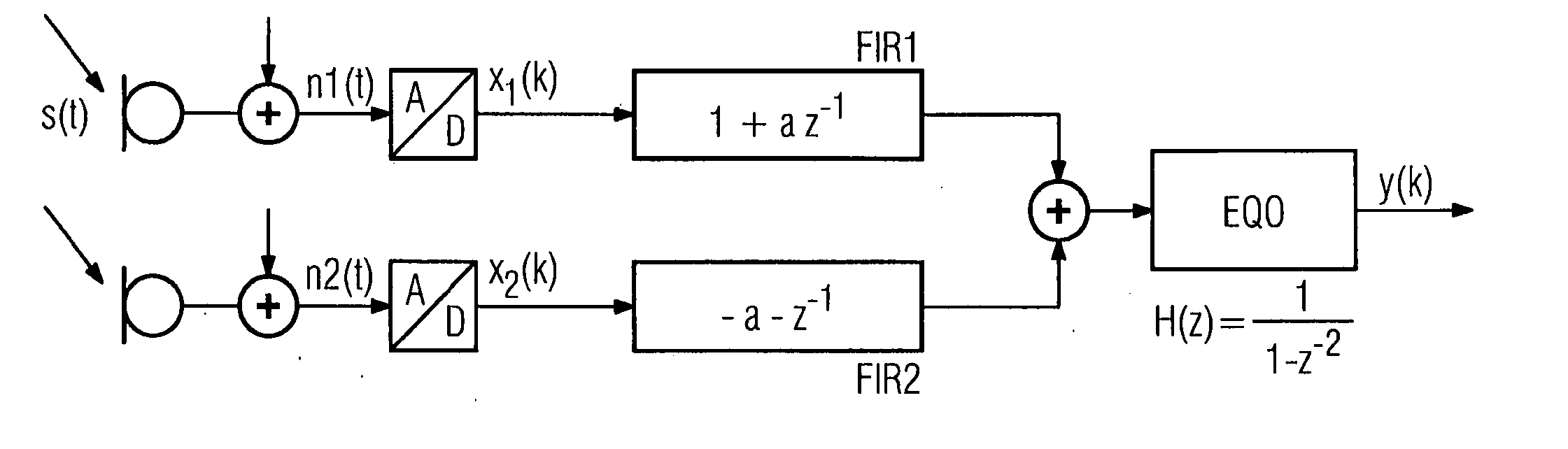
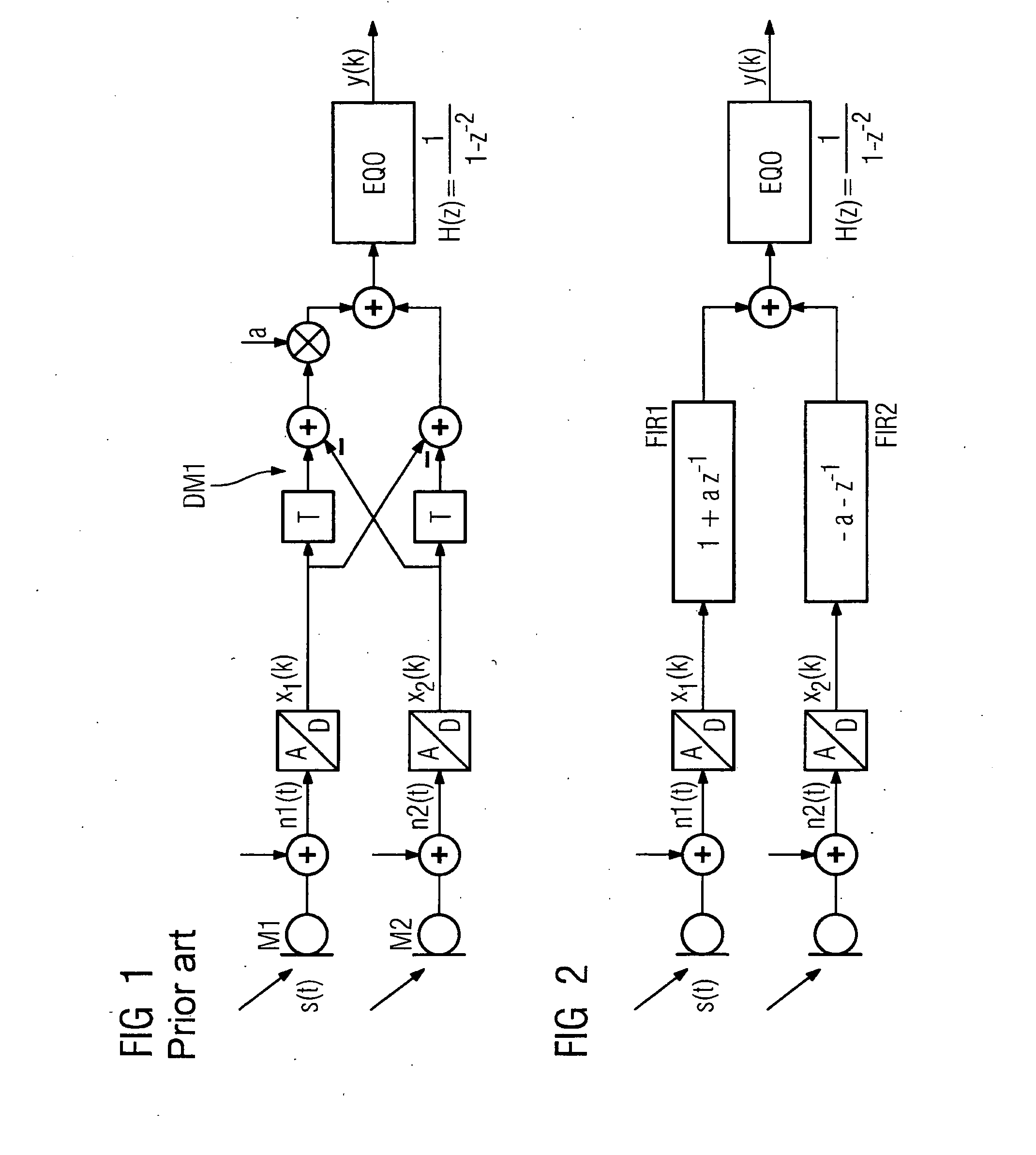
[0025] To aid understanding of the present invention, a first order differential microphone according to the prior art is first explained with reference to FIG. 1. Two microphones M1 and M2 receive a time-dependent acoustic signal s(t). A microphone noise signal n1(t) and / or n2(t) is added in each instance to the ideal microphone sign als. The respective summation signals are digitalized with an analogue digital converter thereby resulting in microphone signals x1(k) and x2(k). A first order differential microphone subtracts the two microphone signals x1(k) and x2(k) in a crosswise fashion, as is known for directional microphones. In this case, the signals are delayed in the corresponding paths with timing elements T and a difference signals is multiplied with an adaptation parameter a. The resulting signals are added and supplied to an equalizer EQ0 with th...


PUM


Abstract

The interference powers with directional microphones are to be suppressed as far as possible. To this end, provision is made to adaptively filter the microphone of a number of microphones as a function of at least one parameter. The directional effect of the directional microphone achieved in this way is adjusted by modifying the at least one parameter, such that the summation of interference powers including microphone noises is reduced and/or minimal.

Description

CROSS REFERENCE TO RELATED APPLICATIONS [0001] This application claims priority to the German application No. 10 2004 052 912.4, filed Nov. 2, 2004 which is incorporated by reference herein in its entirety. FIELD OF INVENTION [0002] The present invention relates to a method for reducing interference powers with a directional microphone by means of providing at least two microphone signals adaptive filtering of the at least two microphone signals to achieve a directional effect, with at least one adaptation parameter being able to be optimized. Furthermore, the present invention relates to a corresponding acoustics system with a directional microphone. BACKGROUND OF INVENTION [0003] With acoustic systems essentially and in particular with hearing devices, a plurality of microphone signals are required to be combined spatially and filtered spectrally such that the output signal has the fewest possible interference components. In this case interferences are defined on the one hand as t...

Claims


Application Information

Patent Timeline
IPC IPC(8): H04R3/00H04R1/02
CPCH04R3/005H04R25/407
Inventor FISCHER, EGHARTPUDER, HENNING
Owner SIVANTOS PTE LTD
Why Eureka
Try Eureka