Stud for parts assembly

a technology of parts and screws, applied in the direction of threaded fasteners, screws, fastening means, etc., can solve the problems of weakening the assembly without the mechanic's knowledge, reducing the ease with which objects may be assembled and disassembled, and preventing the articulation of parts

Inactive Publication Date: 2006-05-18
FLEMING DAVID THOMAS
View PDF17 Cites 30 Cited by
  • Summary
  • Abstract
  • Description
  • Claims
  • Application Information

AI Technical Summary

Benefits of technology

[0010] The invention is directed to the use of a cylindrical stud with an Allen, Star, or similar drive recession, drive pocket, or drive receiving aperture in at least one end. This aids in providing a gripping or drive point from which the shaft may be turned or secured without damaging the threads along the stud shaft. Such a stud improves the ease with which objects may be assembled and disassembled while preventing articulation of parts the user desires to keep stationary.

Problems solved by technology

If the stud tightens in the block upon operating a nut at the other end of the stud, it might seize and become difficult or impossible to remove.
Alternatively, the stud may back out of the engine block by disengaging from the receiving threads and weaken the assembly without the mechanic's knowledge.
It is also preferred that the end of the stud be flush with the outer surface of the assembly which further complicates gripping the stud.

Method used


Image

  • Stud for parts assembly
  • Stud for parts assembly
  • Stud for parts assembly

Examples


Embodiment Construction

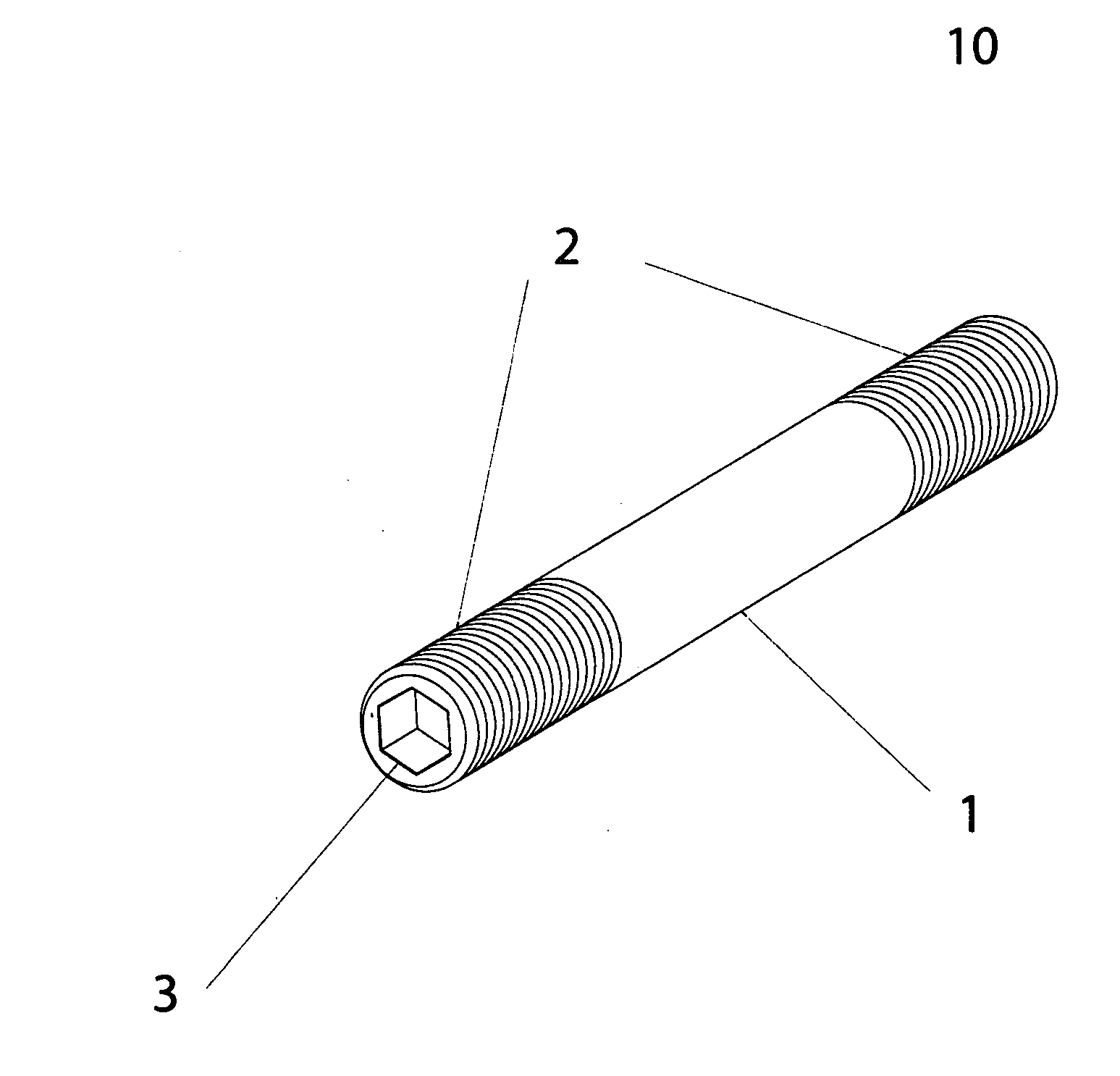
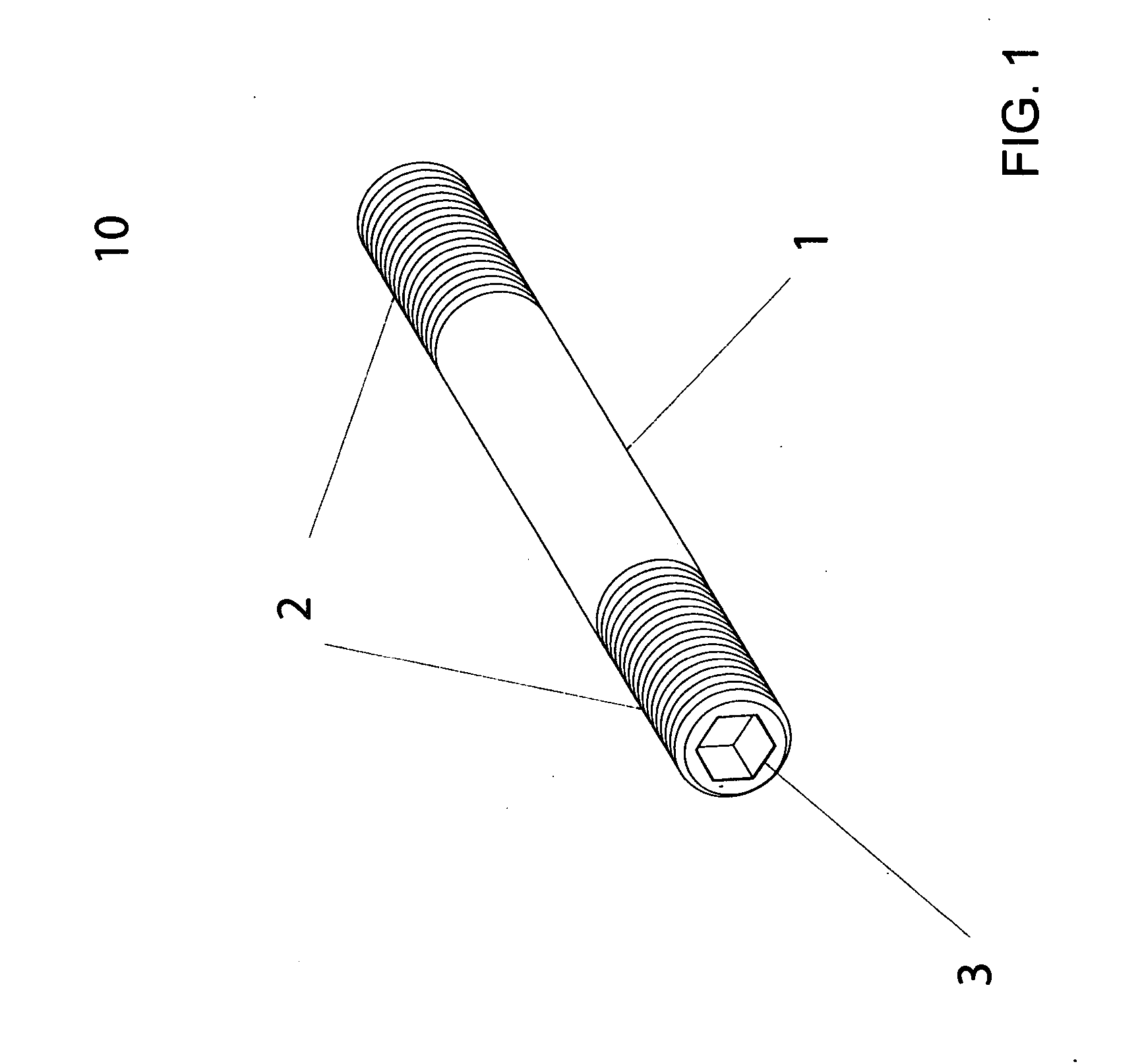
[0021] With reference to FIG. 1, a preferred embodiment of an improved stud in accordance with the present invention is shown by reference numeral 10, the basic structure of which includes a cylindrical shaft 1, threaded surfaces 2 on opposing ends of the shaft 1, and a drive recession, drive pocket, or drive receiving aperture 3.

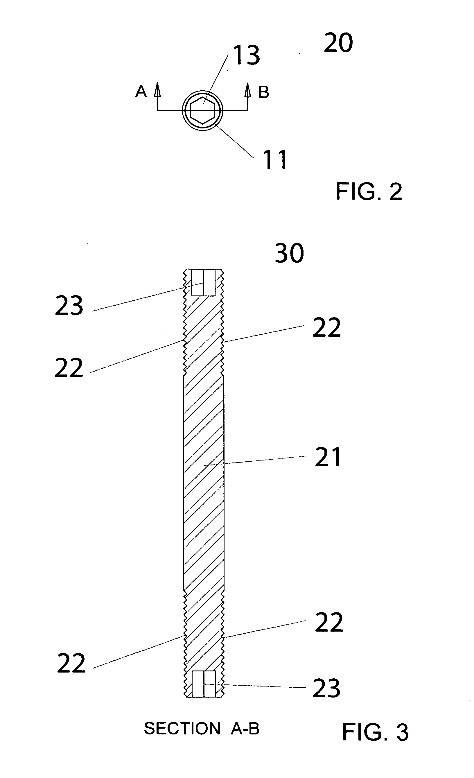
[0022] With reference to FIG. 2, the drive recession, drive pocket, or drive receiving aperture 13 can be seen in this end view of the cylindrical shaft 11 of the present invention 20. A plane across the width of the shaft 11 is depicted along the A-B plane.

[0023] With reference to FIG. 3, the preferred embodiment of the present invention 30 is depicted as a cross-section along the shaft 21 and the A-B plane of FIG. 2. Depicted are the drive recession, drive pocket, or drive receiving aperture 23 that is intended in this embodiment to receive an alien head drive, a threaded surface 22.


PUM


Abstract

An improved stud for assembling an engine valve cover or other mechanical parts together comprised of an elongated shaft having two end portions and at least one intermediate threaded portion therebetween. At least one end portion of the stud has a drive receiving recess formed therein. The intermediate threaded portion may be a single continuous thread or two distinct threads. The pitch and spacing on the thread or threads need not be identical and are ideally matched to the receiving threads of an orafice. The drive pocket in the head of the stud allows the shaft to be installed and removed by applying torque to the end and not to the body of the stud along the shaft. The stud may also be securely held so as not to be loosened or removed from one set of receiving threads into which it is installed while an object is installed or removed from the threads on the opposing end.

Description

BACKGROUND OF THE INVENTION [0001] 1. Field of the Invention [0002] This invention relates to a threaded stud with a drive recession in at least one end of the stud shaft. The stud may be threaded with a continuous thread along the shaft or may utilize more than one thread of the same or different pitches and spacing. The stud is twisted into a threaded orafice by inserting a fitted drive tool into the drive pocket and applying rotational force at the end of the stud. The drive tool can also hold the stud stationary while a nut or similar object is installed or removed from the stud shaft. [0003] The drive recession in the head or opposing end of the stud shaft may be of any design to receive a fittedly designed tool matching said recession. Non-limiting examples of such a recession are an Allen head or Star head shaped recession. Anticipated uses include, but are not limited to, a fastening or securing means for home, industrial, and automotive applications. [0004] 2. Problems in t...

Claims


Application Information

Patent Timeline
Patent Type & Authority Applications(United States)
IPC IPC(8): F16B35/00
CPCF16B5/0275F16B23/0038F16B35/045
Inventor FLEMING, DAVID THOMAS
Owner FLEMING DAVID THOMAS
Why Eureka
Try Eureka