Plasma display apparatus and driving method of the same

a technology of plasma display and driving method, which is applied in the direction of instruments, static indicating devices, etc., can solve the problems of reducing the contrast ratio, abnormal discharge or erroneous discharge, and reducing the contrast of darkroom, so as to reduce noise, stabilize discharge, and suppress the generation of erroneous discharge

Inactive Publication Date: 2006-05-25
LG ELECTRONICS INC
View PDF7 Cites 10 Cited by
  • Summary
  • Abstract
  • Description
  • Claims
  • Application Information

AI Technical Summary

Benefits of technology

[0067] The present invention can reduce noise, and stabilize discharges of a PDP in a high temperature environment, thereby suppressing generation of an erroneous discharge depending on temperature related.

Problems solved by technology

However, in the conventional plasma display apparatus, there is a drawback in that, during the erasure period (EP) of the (n-1)th subfield (SFn-1) and the reset period (RP) of the nth subfield (SFn), the discharge is generated several times to initialize the discharge cells 1 and to control the wall charges, thereby reducing the darkroom contrast and reducing a contrast ratio.
If the dark discharge is not generated in the setup period (SU), the discharge cell is not in the optimal address condition soon after the reset period, thereby causing an abnormal discharge or an erroneous discharge.
In other words, when the erasure discharge is strongly generated in the erasure period prior to the reset period, an erroneous discharge can occur.
As a result, where the erasure discharge is very weak or is not generated in the erasure period prior to the reset period, the initialization is not performed properly, thereby causing an erroneous discharge or an abnormal discharge.
If the initial gap voltage (Vgini) does not satisfy the condition of the Equation 4 before the setup period (SU), the conventional plasma display apparatus can cause an erroneous discharge, a mistaken discharge, or an abnormal discharge and a decrease in the operational margin.
In other words, in the conventional plasma display apparatus, to secure the operational reliability and the operation margin, an erasure operation in the erasure period (EP) should be normally performed but, as aforementioned, can be abnormally performed depending on the uniformity of the discharge cell or the use temperature of the PDP.
In the conventional plasma display apparatus, there is a drawback in that, due to excessive space charges apprearing in a high temperature environment and the active motion of the space charges, the wall charge distribution becomes unstable, thereby causing the erroneous discharge, the misdischarge, or the abnormal discharge and therefore, the operational margin decreases.
Accordingly, there is a drawback in that, when the driving waveform of FIG. 4 is applied to a PDP used in a high temperature environment, mistaken writing of the on-cells will occur frequently.
The noise is generated due to coupling through the capacitance of a PDP.
As mentioned above, there is a drawback in that the scan pulse applied to the scan electrode (Y) and concurrently, the data pulse applied to the address electrode (X) result in noise being generated in the waveform applied to the scan electrode (Y) and the sustain electrode (Z) which then causes an unstable address discharge to be generated in the address period, thereby reducing the driving efficiency of the plasma display panel.
In the conventional plasma display apparatus driven using the driving waveform, the erroneous discharge is generally caused by a temperature around the panel that is high.
Referring to FIG. 11, in the plasma display apparatus operating by the driving waveform according to the conventional driving method, when the temperature around the panel is relatively high, a recombination ratio of the space charges 401 to the wall charges 400 within the discharge cell is increased, and an absolute amount of the wall charges participating in the discharge decreases, thereby causing the erroneous discharge.
Therefore, the address discharge is more unstable.
Accordingly, a high temperature erroneous discharge occurs, thereby turning-off the turned-on discharge cell of the address period, in the sustain period.
Accordingly, there is a drawback in that after any one sustain discharge, the recombination of the space charges 401 and the wall charges 400 causes the wall charges 400 participating in the sustain discharge to decrease in amount, thereby causing the high temperature erroneous discharge that does not generate a next sustain discharge.

Method used


Image

  • Plasma display apparatus and driving method of the same
  • Plasma display apparatus and driving method of the same
  • Plasma display apparatus and driving method of the same

Examples


first embodiment

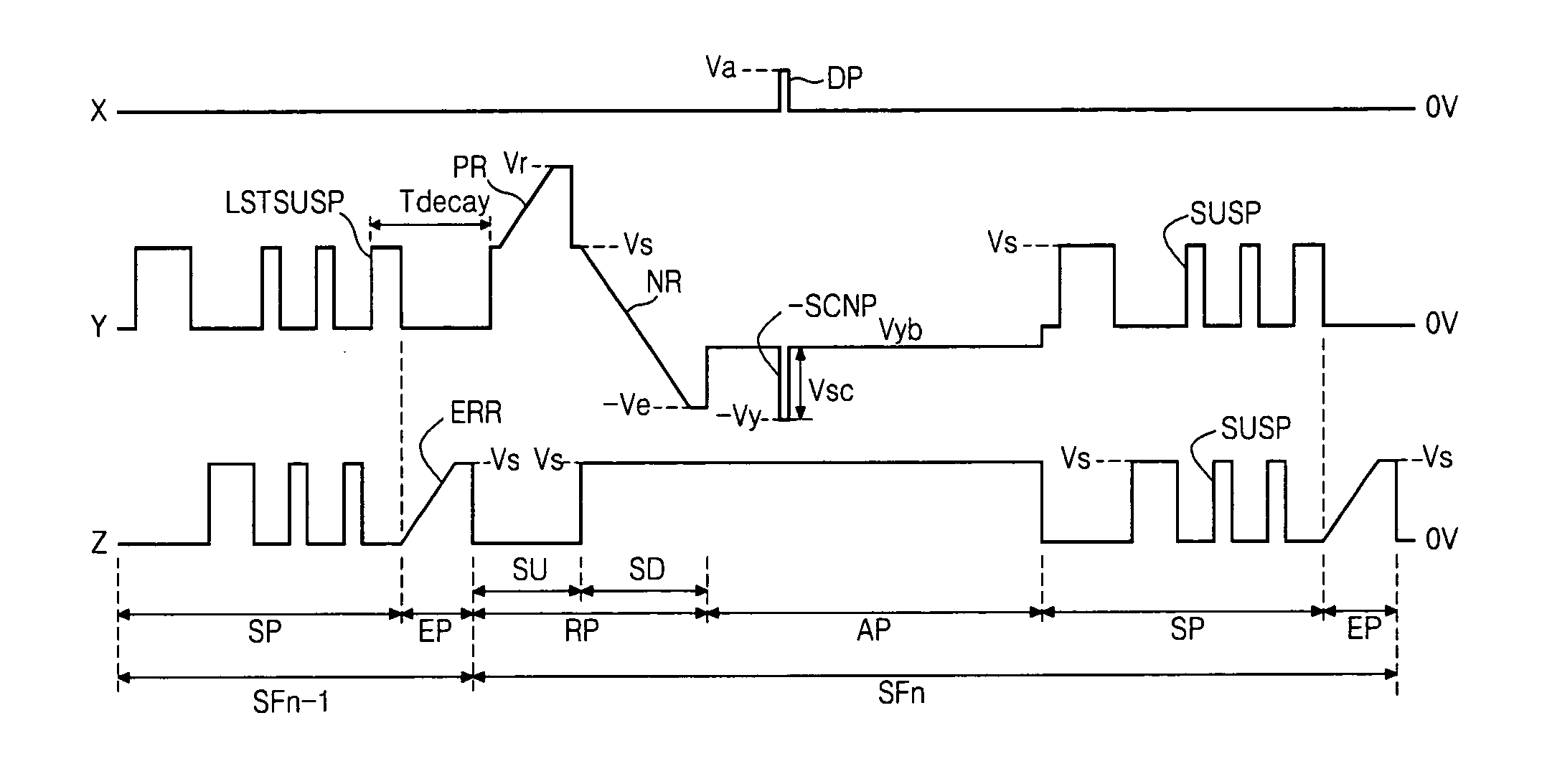
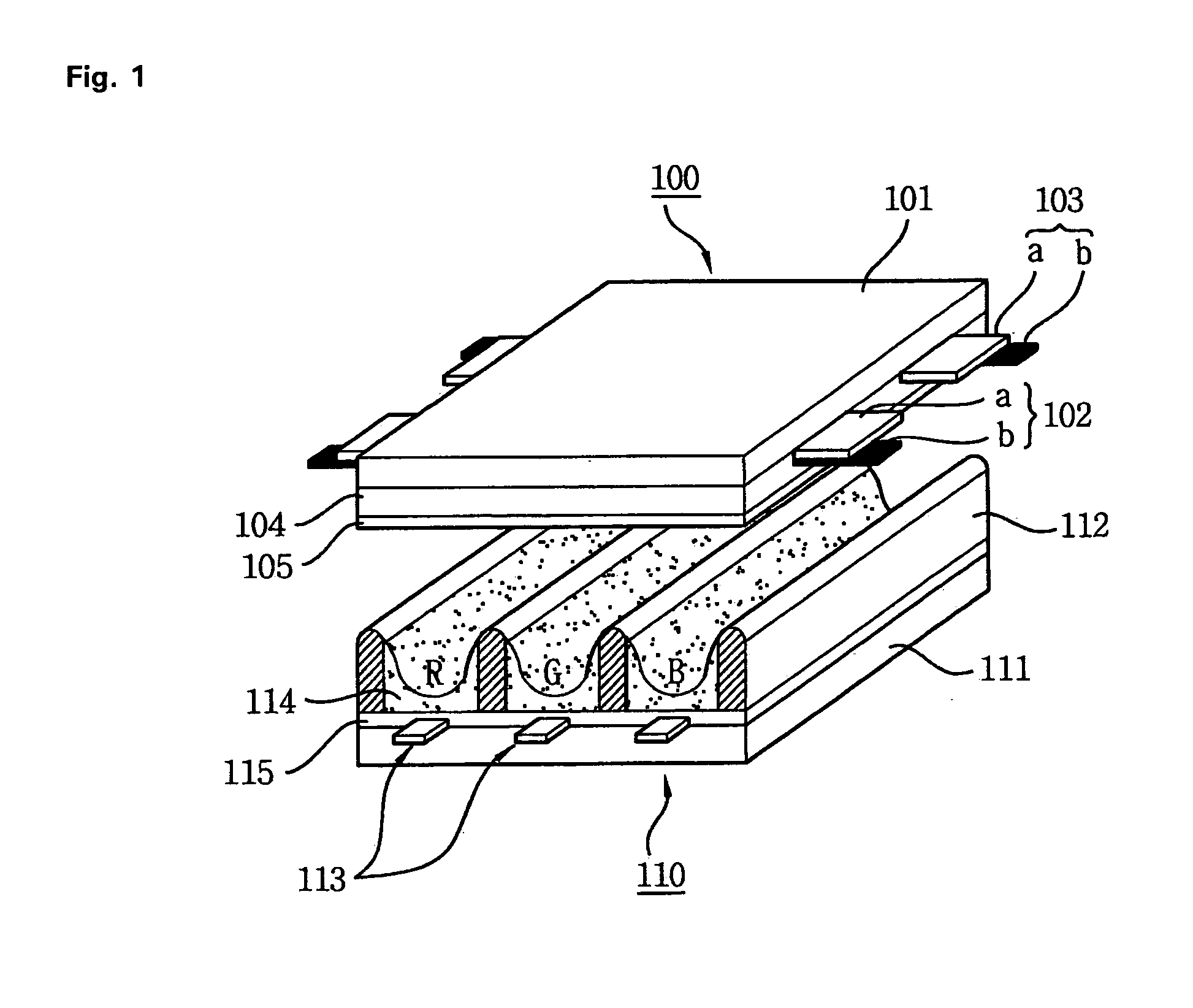
[0103]FIG. 12 is a waveform diagram illustrating a driving method of a plasma display apparatus according to the present invention. A driving waveform of FIG. 12 is applied to a three-electrode alternating current surface discharge type plasma display panel (PDP) shown in FIG. 2.

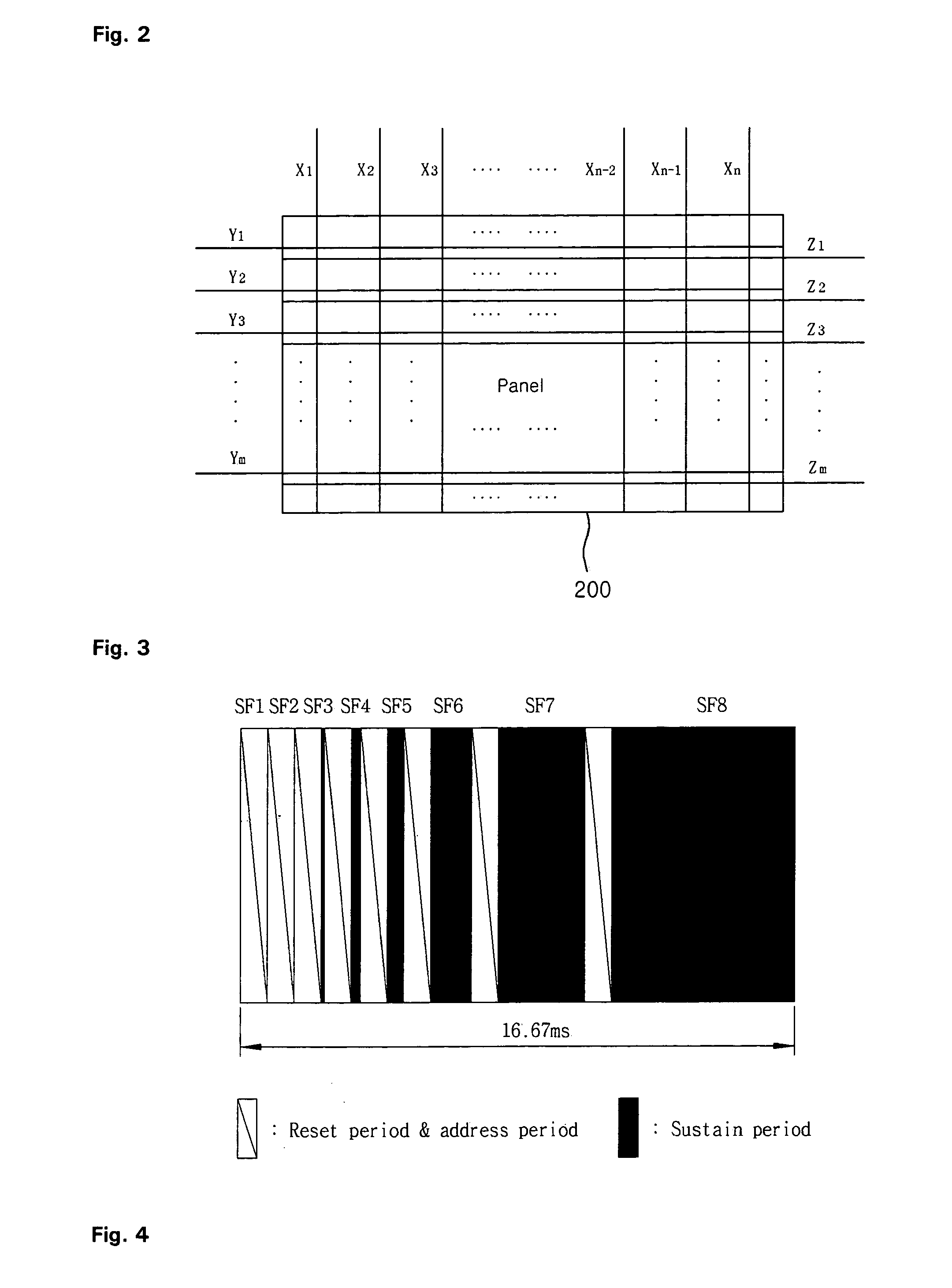
[0104] Referring to FIG. 12, each subfield (SFn-1 and SFn) includes a reset period (RP) for initializing discharge cells of a whole screen, an address period (AP) for selecting the discharge cell, a sustain period (SP) for sustaining discharge of the selected discharge cell and an erasure period (EP) for erasing the wall charges within the discharge cell.

[0105] The reset period (RP), the address period (AP), and the sustain period (SP) are the same as those of the driving waveform of FIG. 4 and therefore, a detailed description thereof will be omitted.

[0106] In the driving method of the plasma display apparatus according to the first embodiment of the present invention, in a high temperature environment of...

second embodiment

[0109]FIG. 13 is a waveform diagram illustrating a driving method of a plasma display apparatus according to the present invention. A driving waveform of FIG. 13 is applicable to a PDP where the discharge cells can be initialized using only a last sustain discharge in a previous subfield and a setdown discharge in a next subfield subsequent to the previous subfield without the setup discharge, that is, to a PDP having the discharge cell with a high uniformity and a wide driving margin.

[0110] Referring to FIG. 13, an (n-1)th subfield (SFn-1) includes a reset period (RP), an address period (AP), and a sustain period (SP). An nth subfield (SFn) includes a reset period (RP) having only a setdown period without a setup period, an address period (AP), a sustain period (SP), and an erasure period (EP).

[0111] The address period (AP) and the sustain period (SP) are substantially the same as those of the driving waveform of FIG. 4 and the embodiment of FIG. 12 and therefore, detailed descrip...

third embodiment

[0115]FIG. 14 is a waveform diagram illustrating a driving method of a plasma display apparatus according to the present invention, and FIGS. 15A and 15E are stepwise diagrams illustrating a wall charge distribution within a discharge cell varied by a driving waveform of FIG. 14.

[0116] The driving waveform of FIG. 14 will be described on the basis of the wall charge distribution of FIGS. 15A to 15E.

[0117] Referring to FIG. 14, in the driving method of the plasma display apparatus according to the present invention, driving is performed in a high temperature environment by time-dividing at least any one subfield (for example, a first subfield) into a pre reset period (PRERP) for forming a positive wall charge on scan electrodes (Y) and forming a negative wall charge on sustain electrodes (Z), a reset period (RP) for initializing the discharge cells of a whole screen using the wall charge distribution formed by the pre reset period (PRERP), an address period (AP), and a sustain perio...


PUM


Abstract

A plasma display apparatus and a driving method of the same are provided. The plasma display apparatus comprises a plasma display panel comprising a scan electrode, a sustain electrode and an address electrode; a first controller for controlling an application time point of the data pulse for the address electrode during address period to be different from an application time point of a scan pulse for the scan electrode; and a second controller for controlling a last sustain pulse applied to at least one of the scan electrode and the sustain electrode, wherein the second controller controls, when the temperature in the plasma display panel or the temperature around the plasma display panel is substantially a high temperature, an interval between the application time point of the last sustain pulse and an initialization signal of a next subfield to be longer than the interval in room temperature.

Description

[0001] This Nonprovisional application claims priority under 35 U.S.C. § 119(a) on Patent Application No. 10-2004-0095455 filed in Republic of Korea on Nov. 19, 2004, Patent Application No. 10-2005-0068666 filed in Republic of Korea on Jul. 27, 2005, the entire contents of which are hereby incorporated by reference. BACKGROUND OF THE INVENTION [0002] 1. Field of the Invention [0003] The present invention relates to a plasma display apparatus, and more particularly, to a plasma display apparatus and a driving method of the same, for preventing an erroneous discharge, a mistaken discharge, and an abnormal discharge, increasing a dark room contrast, for increasing an operation margin, and for differently embodying application time points of pulses applied in an address period and a sustain period. [0004] 2. Description of the Background Art [0005] In a conventioal plasma display panel, one unit cell is provided at a space between barrier ribs formed between a front panel and a rear pan...

Claims


Application Information

Patent Timeline
Patent Type & Authority Applications(United States)
IPC IPC(8): G09G3/28G09G3/20G09G3/288G09G3/291G09G3/292G09G3/293G09G3/294G09G3/296G09G3/298
CPCG09G3/2022G09G3/2927G09G3/2932G09G3/294G09G2310/0218G09G2320/0228G09G2320/0238G09G2320/041G09G2320/066
Inventor JUNG, YUNKWON
Owner LG ELECTRONICS INC
Why Eureka
Try Eureka