Method, apparatus and system for minimally intrusive fiber identification

a fiber identification and minimal intrusion technology, applied in the field of methods, can solve problems such as the management of optical fibers of a telecommunication office, the disruption of service to many circuits, and the simultaneous presence of many customers

Active Publication Date: 2006-05-25
AMERICAN TELEPHONE & TELEGRAPH CO
View PDF7 Cites 3 Cited by
  • Summary
  • Abstract
  • Description
  • Claims
  • Application Information

AI Technical Summary

Benefits of technology

[0043] Therefore, to exploit the advantages of the present invention while minimizing the system impact (recalling that the loss may vary strongly with wavelength), various embodiments of the present invention comprise a means for providing an adjustable bending radius to optical fibers and thus, adjustable bending losses for varied applications. For instance, an embodiment of a fiber identification device of the present invention may comprise various fiber bending devices (e.g., anvils), each possessing a different radius of curvature. As such, when an accurate DC measurement must be made on a fiber wherein loss is not too great an issue, a smaller radius anvil would be implemented. The smaller radius anvil would impose more loss on the fiber, but would insure accuracy by diverting more power to the detector. Such a method is preferable for applications in tracing, characterizing, and inventorying dark fibers, for example, where loss is not an issue.

Problems solved by technology

As capacity increases, problems arise in the management of the optical fibers of a telecommunication office.
Specifically, because optical fibers transport large amounts of high bit-rate traffic, the disruption of such traffic leads to the disruption of service to many circuits and, as such, to many customers simultaneously.
The unidentified or mis-identified fiber connections can ultimately lead to disastrous Quality of Service conditions.
If the fiber connection is mislabeled or unknown, the technician may in fact be disrupting a properly functioning circuit, thus creating a new error and disruption of service and delaying the repair of the original faulted circuit.
This causes deterioration of a signal that is to be transmitted by the bent fiber.
Therefore, if the LI method is applied during transmission of an optical signal, troubles such as channel interruption will occur in optical signal communication, and in an extreme case, cracking might occur in the coated fiber.
In addition, if light having a power greater than a threshold level is injected into a fiber by the LI method, the injected light may be transmitted to an office or to subscribers resulting in the addition of a noise component that may deteriorate an optical signal being transmitted.

Method used


Image

  • Method, apparatus and system for minimally intrusive fiber identification
  • Method, apparatus and system for minimally intrusive fiber identification
  • Method, apparatus and system for minimally intrusive fiber identification

Examples


Embodiment Construction

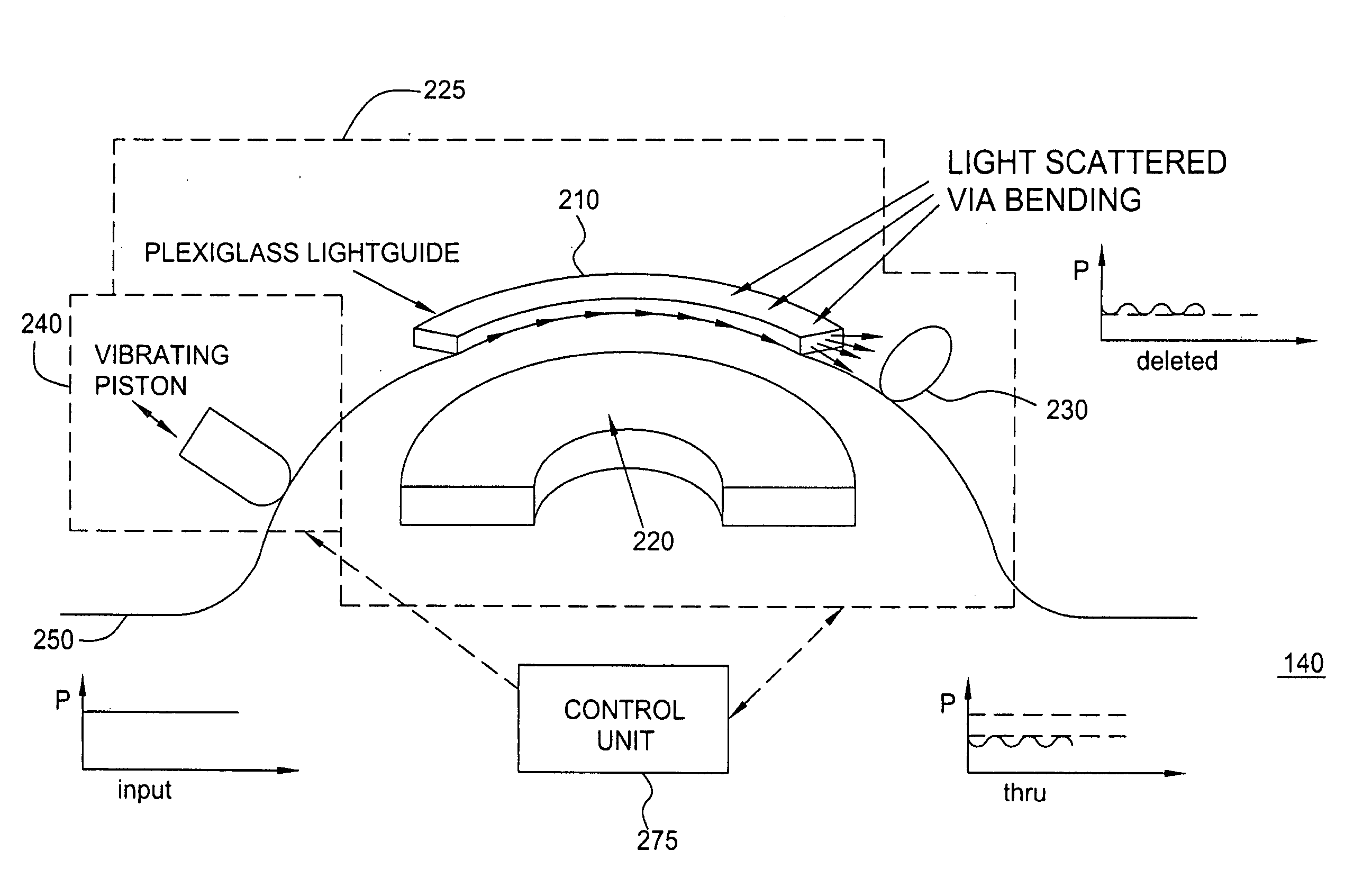
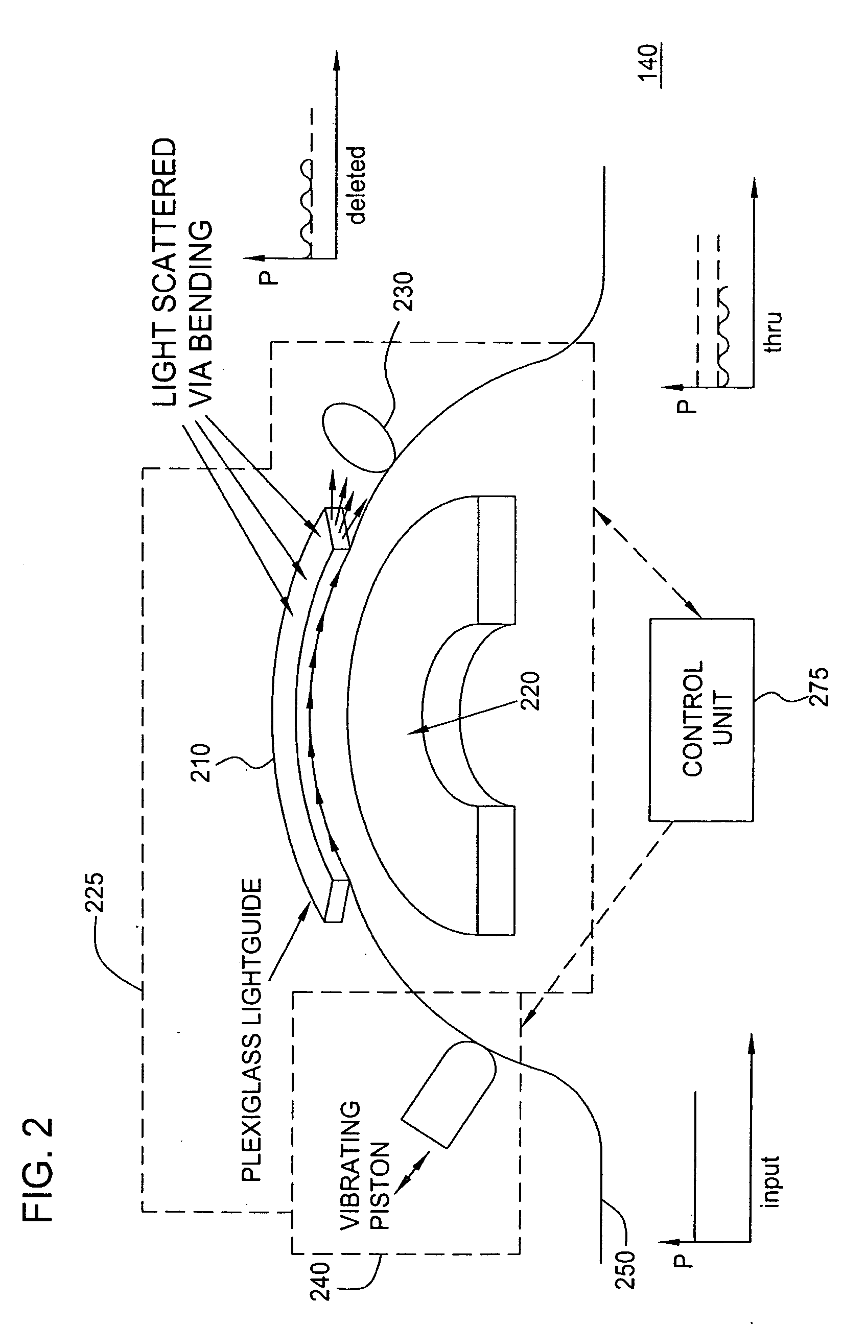
[0019] Although various embodiments of the present invention herein are being described with respect to optical fibers within a telecommunications office, it should be noted that the optical fibers and the telecommunications office presented herein are simply provided as exemplary working environments wherein various embodiments of the present invention may be applied and should not be treated as limiting the scope of the invention. It will be appreciated by those skilled in the art informed by the teachings of the present invention that the concepts of the present invention may be applied to a single or multiply-interconnected optical fibers (or waveguides) in substantially any working environment (local or remote) for the identification of the transmission medium.

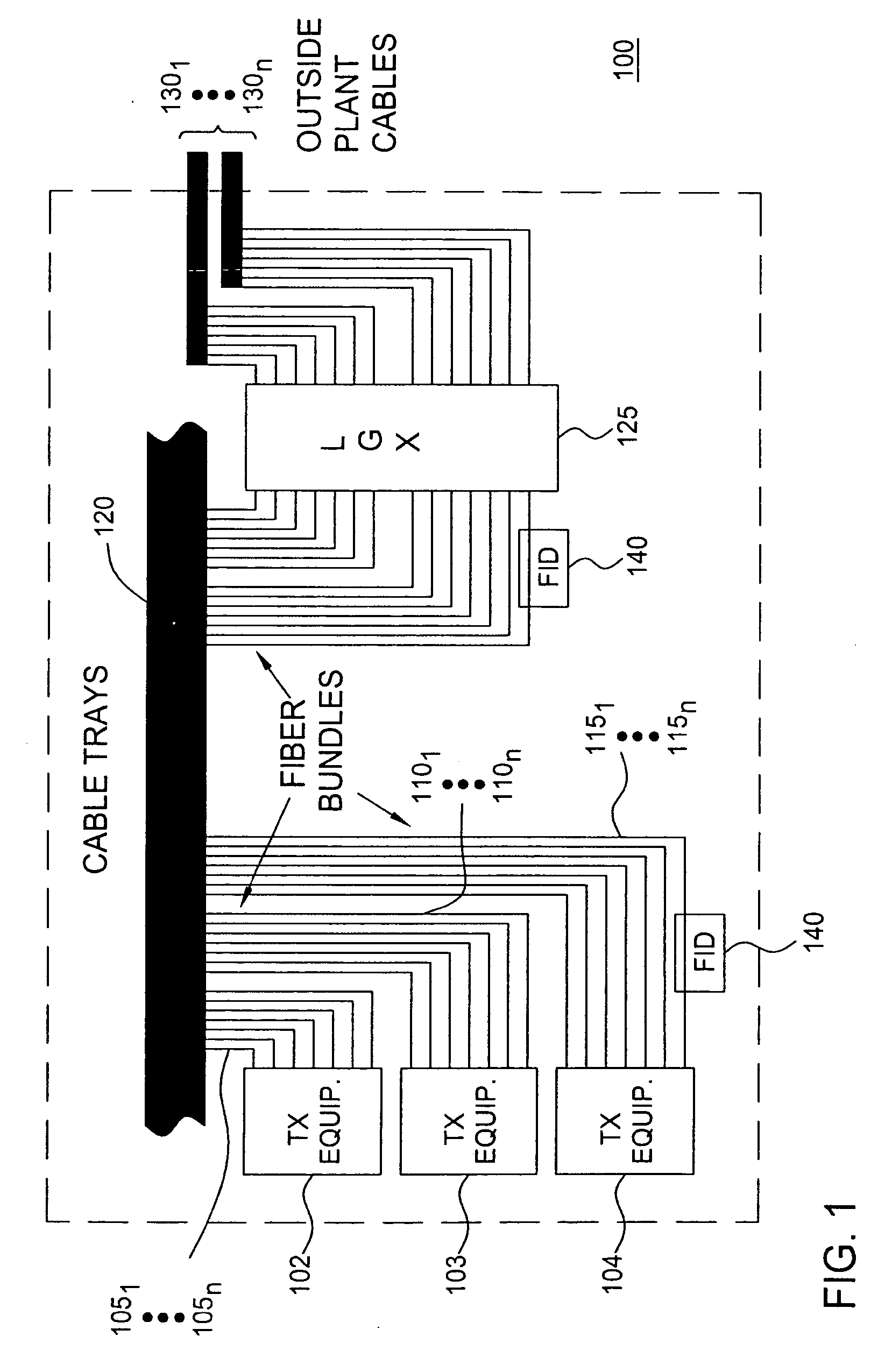
[0020]FIG. 1 depicts a high level block diagram of a telecommunications office wherein an embodiment of the present invention may be applied. The telecommunications office 100 of FIG. 1 illustratively comprises three rac...


PUM


Abstract

A method, apparatus and system for minimally intrusive fiber identification includes imparting a time-varying modulation onto an optical signal propagating in an optical fiber and subsequently detecting the presence of the time-varying modulation in the optical signal transmitting through the fiber to identify the fiber. In a specific embodiment of the invention, a time-varying curvature is imposed on the fiber to be identified and the presence of the resultant time variation in the transmitted power of a propagating optical signal is subsequently detected for identification of the manipulated fiber.

Description

CROSS-REFERENCES TO RELATED APPLICATIONS [0001] This application is a divisional of co-pending U.S. Non-Provisional application Ser. No. 10 / 750,448, filed Dec. 31, 2003 and claims the benefit of U.S. Provisional Application No. 60 / 496,448, filed Aug. 20, 2003, which is herein incorporated by reference in its entirety.FIELD OF THE INVENTION [0002] The present invention relates generally to fiber identification and, more particularly, to a method, apparatus and system for identifying fibers that minimally intrudes with optical signals propagating therein. BACKGROUND OF THE INVENTION [0003] Modern telecommunications offices have evolved in recent years to accommodate greater volumes of traffic, thus placing larger and larger amounts of equipment (usually connected by optical fibers) in areas of limited space. In addition to the increasing numbers of optical fibers, traffic carried by each of the optical fibers is also ever-increasing. As capacity increases, problems arise in the manage...

Claims


Application Information

Patent Timeline
Patent Type & Authority Applications(United States)
IPC IPC(8): G02B6/00G02B6/44H04B10/08
CPCG01M11/088G02B6/2852G01M11/30H04B10/07G02B6/447G02F1/095G02B6/562G02B6/00G01M11/00G01M11/35
Inventor FRIGO, NICHOLAS J.IANNONE, PATRICKREICHMANN, KENNETH C.
Owner AMERICAN TELEPHONE & TELEGRAPH CO
Why Eureka
Try Eureka