Method and apparatus of manufacturing grooved pipe, and structure thereof

a manufacturing method and groove technology, applied in the direction of indirect heat exchangers, lighting and heating apparatus, other domestic articles, etc., can solve the problems of uneven length of pipe, product quality is not stable, and the forming range of grooves in the longitudinal direction of inner pipes is not stable, so as to achieve the effect of manufacturing a grooved pip

Inactive Publication Date: 2006-06-01
DENSO CORP +1
View PDF39 Cites 9 Cited by
  • Summary
  • Abstract
  • Description
  • Claims
  • Application Information

AI Technical Summary

Benefits of technology

[0009] In view of the above-described problems, it is an objective of the present invention to provide a method of effectively manufacturing a grooved pipe.
[0012] It is also an objective of the present invention to provide an apparatus for effectively manufacturing a grooved pipe.
[0016] According to an aspect of the present invention, a method of manufacturing a grooved pipe includes a step of pressing a grooved tool and a step of longitudinally displacing at least one of the grooving tool and the pipe. In the step of pressing, a grooving tool is pressed toward an outer surface of a wall of a pipe in a radially inward direction of the pipe at a first location, which is separated by a first predetermined distance from a first end portion of the pipe. Furthermore, in the step of longitudinally displacing, at least one of the grooving tool and the pipe is relatively displaced in a longitudinal direction of the pipe while pressing the grooving tool toward the outer surface of the wall of the pipe to form a groove portion, which is recessed from the outer surface of the wall of the pipe. Accordingly, a groove portion having a predetermined shape can be easily uniformly formed regardless of the pipe length.
[0023] According to another aspect of the present invention, a production apparatus for forming a grooved pipe includes a supporting member which support a pipe, a grooving tool which is disposed to press an outer wall of the pipe toward radially inward of the pipe and to form a groove portion on the outer wall, a pressing tool which is disposed to press the grooving tool to the outer wall toward radially inward, and a longitudinal displacing member through which at least one of the pipe and the grooving tool is relatively displaceable in a longitudinal direction of the pipe while the grooving tool presses the outer wall of the pipe. Therefore, the grooved pipe can be readily formed using the production apparatus.
[0025] According to another aspect of the present invention, a production apparatus for forming a grooved pipe includes a rolling member which is disposed to press an outer wall of a pipe toward radially inward of the pipe, and a displacing member through which at least one of the pipe and the rolling member is relatively displaced. In the production apparatus, the rolling member rolls on the outer wall of the pipe while being pressed to the outer wall to form a groove portion on the outer wall of the pipe. Therefore, the grooved pipe having a uniform groove shape can be stably formed regardless of the grooved pipe length.

Problems solved by technology

However, a groove forming range in a longitudinal direction of the inner pipe is not stable because the screw thread is projected as well as the groove is recessed to form a grooved inner pipe by twisting the inner pipe.
Also, a product quality is not stabilized because a shape of the groove is uneven.
A length of the diameter of the pipe is also uneven because the screw thread is projected radially outward of the pipe.
Therefore, it is difficult for the conventional grooved pipe to meet a market demand because of at least one of above-described disadvantages.
It is also disadvantageous that a projecting part of the inner pipe is strongly pressed toward the outer pipe when the double-wall pipe is formed.
Thus, the conventional method is difficult to be used for twisting a long pipe.
This results in an increase of a number of components and a number of processing.

Method used


Image

  • Method and apparatus of manufacturing grooved pipe, and structure thereof
  • Method and apparatus of manufacturing grooved pipe, and structure thereof
  • Method and apparatus of manufacturing grooved pipe, and structure thereof

Examples


first embodiment

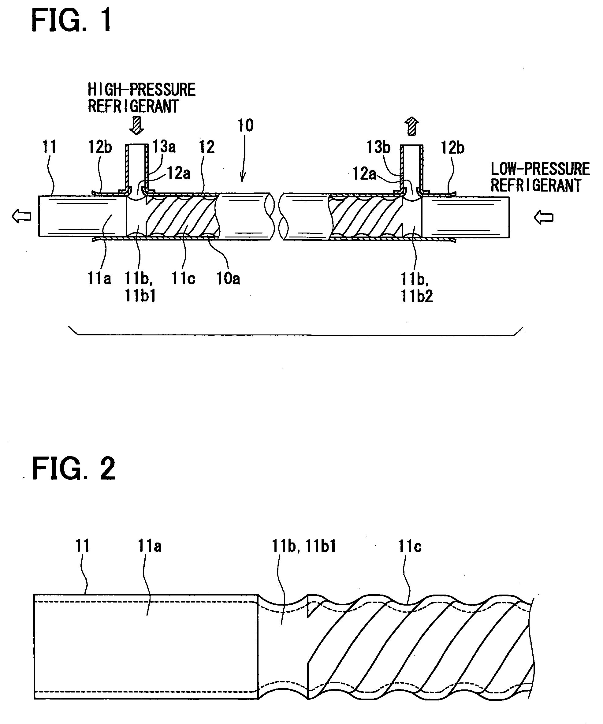
[0035] In this embodiment, a double-wall pipe 10 according to the present invention is typically used for a refrigeration cycle of a vehicle air conditioning apparatus. The double-wall pipe 10 serves as a pipe for a refrigerant. The double-wall pipe 10 also serves as an internal heat exchanger for exchanging heat between a high-temperature high-pressure refrigerant from a condenser of the refrigeration cycle and a low-temperature low-pressure refrigerant from an evaporator. The double-wall pipe 10 is constructed with an outer pipe 12 and an inner pipe 11 inserted into the outer pipe 12. The low-temperature low-pressure refrigerant flows through inside the inner pipe 11. The high-temperature high-pressure refrigerant flows through a passage between the inner pipe 11 and the outer pipe 12. The inner pipe 11 of the double-wall pipe 10 includes grooves 11b, 11c. The grooves 11b, 11c are formed to be recessed from a wall surface 11a of the inner pipe 11. The grooves 11b, 11c are formed b...

second embodiment

[0062] A second embodiment of the present invention will be described with reference to the accompanying drawings. Similar components of a production apparatus forming a grooved pipe of the present embodiment, which are similar to the components of the production apparatus of the grooved pipe of the first embodiment, will be indicated by the same numerals.

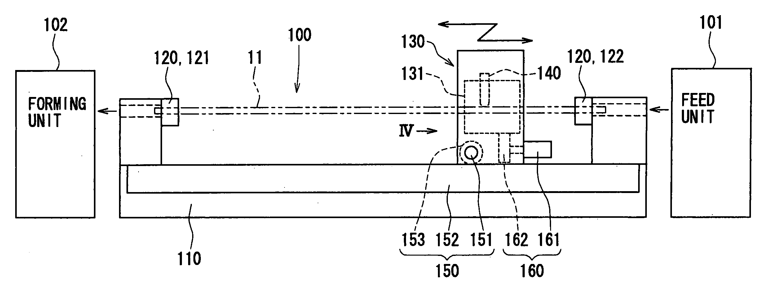
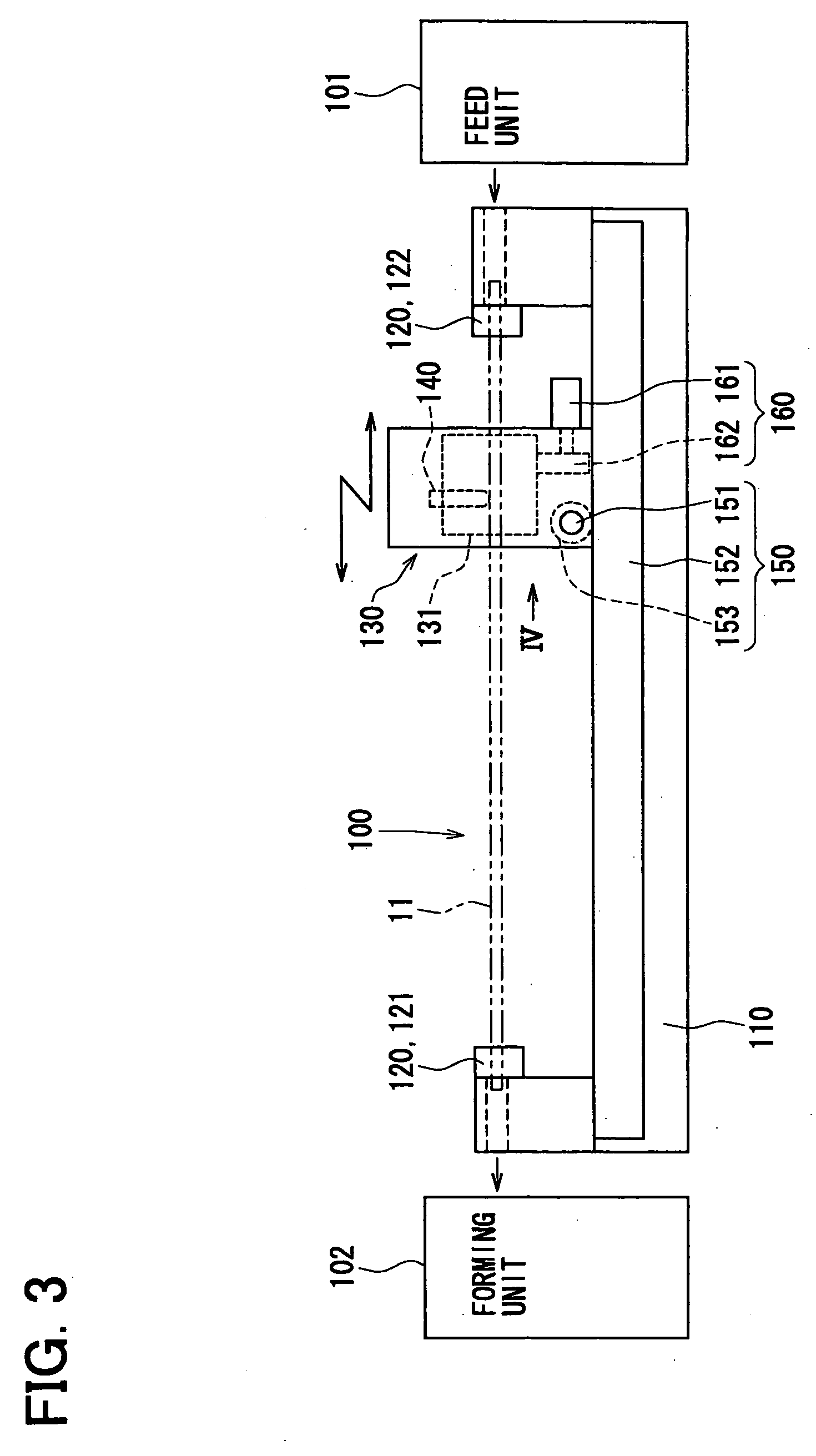
[0063]FIG. 7 is a block diagram of a production method for manufacturing the grooved pipe according to the second embodiment. In the present embodiment, the production apparatus 100 shown in FIGS. 3, 4 can be used, and a displacement of the blocks 131 in the radial direction is driven by a driving device, such as a motor.

[0064] In a feeding step 710, a pipe material to be processed for forming the inner pipe 11 is fed. In a cutting and forming step 711, a predetermined length of the pipe material is cut from a pipe coil. The cut pipe material is formed into a tubular shape to be fed. In a feeding and inserting step 712, the pipe ...


PUM

PropertyMeasurementUnit
lengthaaaaaaaaaa
inner diameteraaaaaaaaaa
outer diameteraaaaaaaaaa

Abstract

A method of manufacturing a grooved pipe includes a pressing step and a longitudinally displacing step. The pressing step presses a grooving tool toward an outer surface of a wall of a pipe in a radially inward direction of the pipe at a location, which is separated by a predetermined distance from an end portion of the pipe. The longitudinally displacing is performed by longitudinally displacing at least one of the grooving tool and the pipe relatively in a longitudinal direction of the pipe while pressing the grooving tool toward the outer surface of the wall of the pipe to form a groove portion, which is recessed from the outer surface of the wall of the pipe. The method is suitably used for forming an inner pipe of a double-wall pipe.

Description

CROSS REFERENCE TO RELATED APPLICATION [0001] This application is based on and incorporates herein by reference Japanese Patent Applications No. 2004-325522 filed on Nov. 9, 2004, No. 2004-325521 filed on Nov. 9, 2004, No. 2005-112825 filed on Apr. 8, 2005, No. 2005-136390 filed on May 9, 2005 and No. 2005-263967, filed on Sep. 12, 2005. BACKGROUND OF THE INVENTION [0002] 1. Field of the Invention [0003] The present invention relates to a method and apparatus for manufacturing a grooved pipe, and relates to a structure of a grooved pipe. The structure of the grooved pipe is suitably used for a double-wall pipe. [0004] 2. Description of Related Art [0005] Conventionally, a grooved pipe is known to serve as, for example, an inner pipe, which is included in a double-wall pipe. [0006] Unexamined Japanese Patent Publication No. 2003-329376 discloses a conventional forming method of a grooved pipe for a double-wall pipe. The double-wall pipe includes inner and outer pipes having mutually ...

Claims


Application Information

Patent Timeline
Patent Type & Authority Applications(United States)
IPC IPC(8): B23P17/00
CPCF16L7/00F16L9/18F25B40/00F28D7/106F28F1/06Y10T29/49361F28F1/426F28F2210/06B23P17/02Y10T29/49428Y10T29/49826F28F1/42F25B1/00F28D7/10F28F1/00
Inventor NAKAMURA, FUMIAKIOCHIAI, KINJI
Owner DENSO CORP
Why Eureka
Try Eureka