Ice retaining shot glass system

a shot glass and ice retention technology, applied in the field of double-walled glasses, can solve the problems of not doing a proper job and pulling frozen coolan

Inactive Publication Date: 2006-06-01
BIANCO MARK LO
View PDF15 Cites 11 Cited by
  • Summary
  • Abstract
  • Description
  • Claims
  • Application Information

AI Technical Summary

Benefits of technology

[0017] AN OBJECT of the present invention is to provide an i

Problems solved by technology

Its failing arises in that gravity will pull the frozen cool

Method used


Image

  • Ice retaining shot glass system
  • Ice retaining shot glass system

Examples


first embodiment

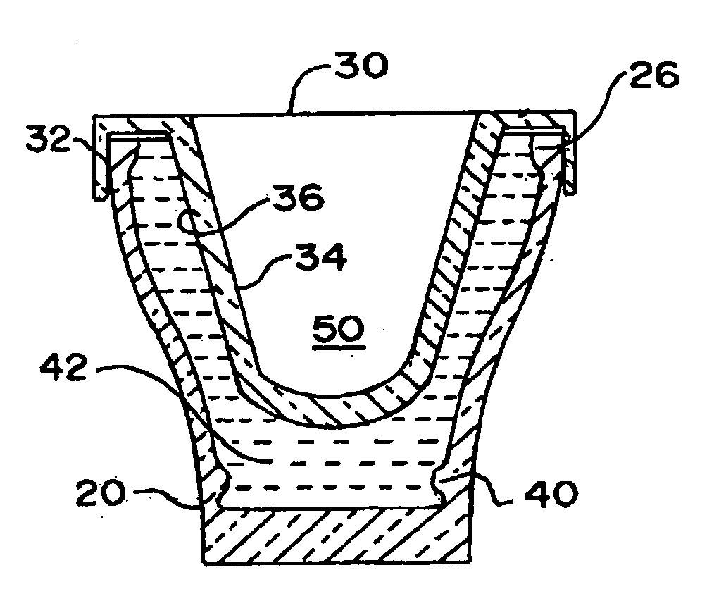
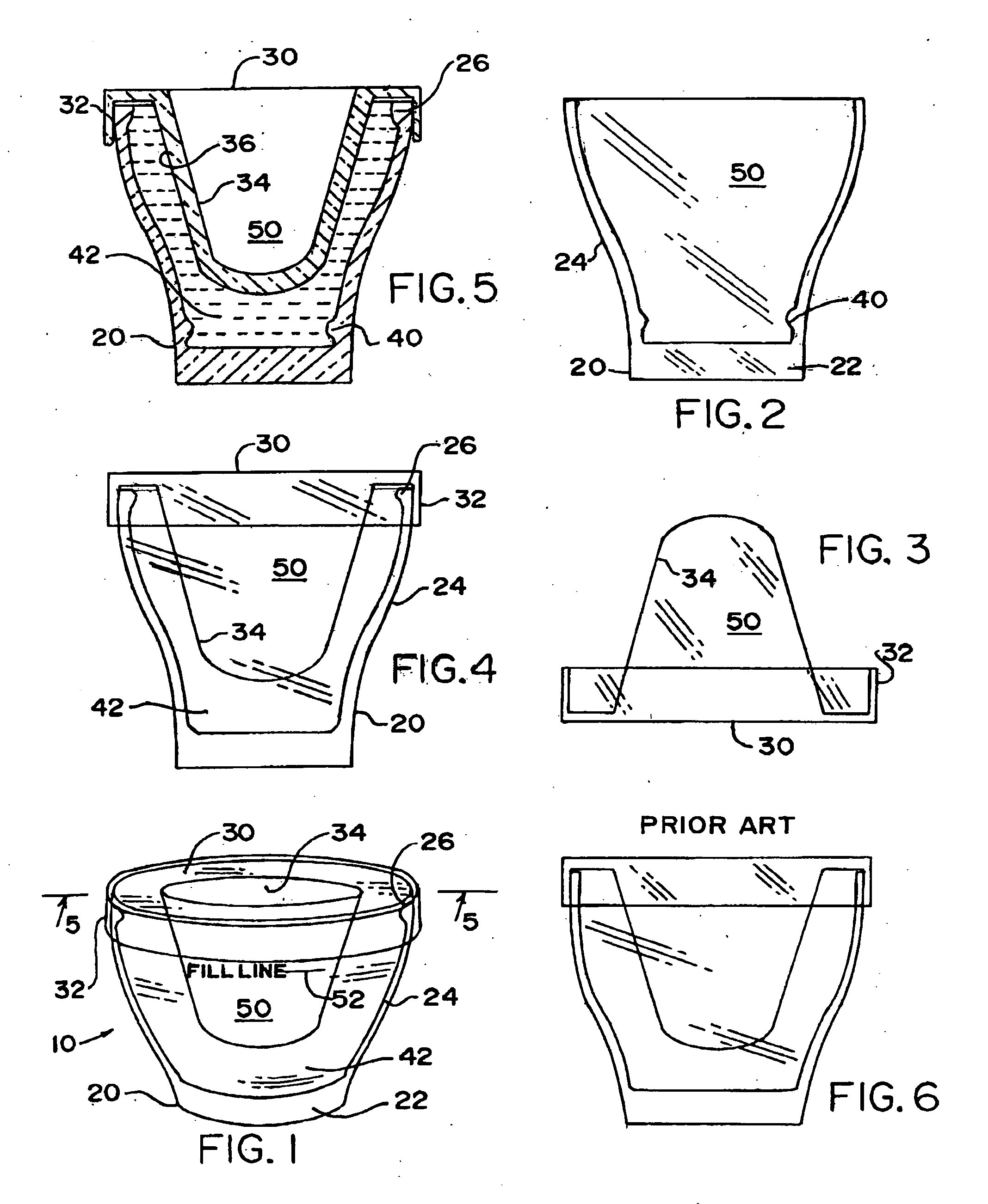
[0045] The instant invention additionally adds novel ice-holding structures to the external wall 2∅. A first embodiment is both lip 26 and detent 4∅ placed upon circumferential wall 2∅. A second such embodiment of al ice holding structure is a circumferential detent 4∅ located (FIG. 2) at the bottom of the exterior wall 2∅ near base 22. Still a third such embodiment is a circumferential lip 26 (FIG. 4) located near the top of wall 2∅.

[0046] In operation, cap 3∅ having shot glass side walls 34 defining an alcohol-retaining area 5∅ is placed over exterior walls 2∅ to form an ice-retaining chamber 42. Cap 3∅ has vertical walls 32 to maintain cap 3∅ in place over and against circumferential walls 2∅.

[0047] Water then fills chamber 42 and is frozen in place.

[0048] Lip 26 and / or circumferential detent 4∅ helps to retain the ice in place even as the ice melts and becomes slushy. Thus, the instant ice shot glass system 1∅ may be repeatedly picked up and set down again upon its base 22 whi...

third embodiment

[0049] It is to be noted that the third embodiment, has an additional benefit of permitting the user to selectively allow the ice chamber to be removable from the shot glass if he / she choose not to sufficiently fill the ice-retaining chamber 42 with respect to the fill line indicia 52 on the shot glass, in which case the ice will not come in contact with the circumferential lip 26 (FIG. 4) located near the top of wall 2∅.

[0050] It will be understood that each of the elements described above, or two or more together, may also find a useful application in other types of constructions differing from the types described above.


PUM


Abstract

A shot glass system has means for holding frozen water, i.e. ice against the alcohol-retaining walls comprising circumferential detents and lips placed within a chamber which is formed adjacent the walls.

Description

BACKGROUND OF THE INVENTION [0001] 1. Field of the Invention [0002] The present invention relates to double-walled glasses and more particularly to shot glasses enclosing ice or cooling means within their walls. [0003] 2. Description of the Prior Art [0004] Numerous innovations for Ice Shot Glasses have been provided in the prior art that will be described. Even though these innovations may be suitable for the specific individual purposes to which they address, accordingly they differ from the present invention. [0005] A FIRST EXAMPLE, U.S. Pat. No. 2,594,127 to Collier teaches an ice cube tray comprising a vessel including top and downwardly directed side walls, spaced cups depending from said top wall defining ice block molds, the depth of said cups being no greater than the height of said side walls, and partitions intermediate certain of said cups attached to the lower face of said top wall and the inner faces of opposed side walls. [0006] A SECOND EXAMPLE, U.S. Pat. No. 4,091,6...

Claims


Application Information

Patent Timeline
IPC IPC(8): F25D3/08
CPCA47G19/2288F25D3/08F25D2303/0831F25D2331/808
Inventor BIANCO, MARK LO
Owner BIANCO MARK LO
Why Eureka
Try Eureka