Occupancy-based circuit breaker control

Active Publication Date: 2006-06-01
SIEMENS ENERGY & AUTOMATION INC
View PDF16 Cites 29 Cited by
  • Summary
  • Abstract
  • Description
  • Claims
  • Application Information

AI Technical Summary

Benefits of technology

[0006] There is provided a method of main circuit breaker system operation using a trip unit coupled to a main circuit breaker capable of being programmed to operate in response to a first set of parameters or a second set of parameters, corresponding to a condition related to the main circuit breaker system. The method comprises the steps of determining the conditions of the main circuit breaker system from an input signal from an input device. Selecting at least one mode of operation of the trip unit corresponding to the input signal. Executing the selected mode of operation of the trip unit, wherein the trip unit will operate in a predetermined manner. Another embodiment of the method includes the step of placing the input device at a predetermined distance from the main circuit breaker. The first set of parameters for the trip unit can be for a maximum system coordination with the second set of parameters set for optimum arc flash reduction.
[0007] There is also provided an occupancy-based control device in a trip unit of a main circuit breaker, with the main circuit breaker coupled to an electrical distribution system including at least one feeder circuit breaker and a load circuit. The occupancy-based control device comprises an input device associated with the electrical distribution system and coupled to the trip unit. A selector apparatus is coupled to the trip unit and configured to select a first set of parameters and a second set of parameters, with each set of parameters defining a mode of operation of the trip unit. A means for selecting one of the first set of parameters and a second set of parameters in respons

Problems solved by technology

In the event that personnel, a human being, has to enter the area where a short circuit or work on an electrical machine is needed, there is a possibility of arc flash from the surrounding “live” circuitry.
If a human being is in the vicinity of such arc flash hazard, bodily injury, including death can result.
Before personnel could approach electrical gear within such designated flash protection boundary, the personnel would be required to wear fire-retardant arc flash suits which are hot, expensive and limit the personnel's ability to work on the electrical equipment.
Such procedure is expensive and inefficient.

Method used


Image

  • Occupancy-based circuit breaker control
  • Occupancy-based circuit breaker control
  • Occupancy-based circuit breaker control

Examples


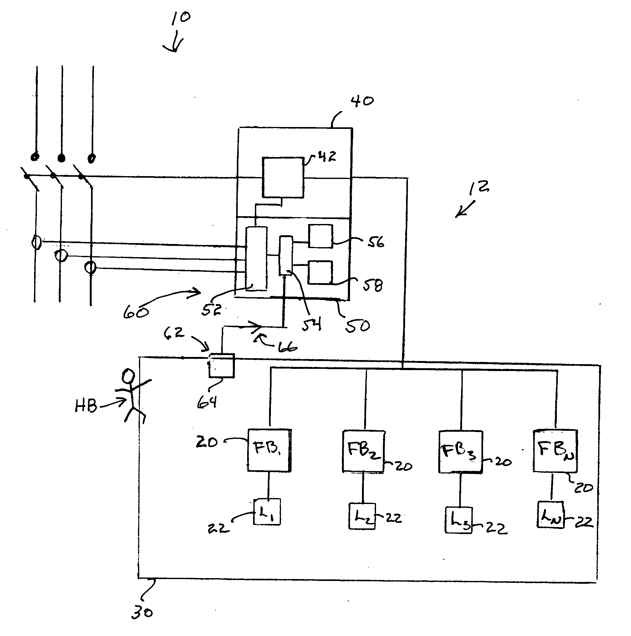
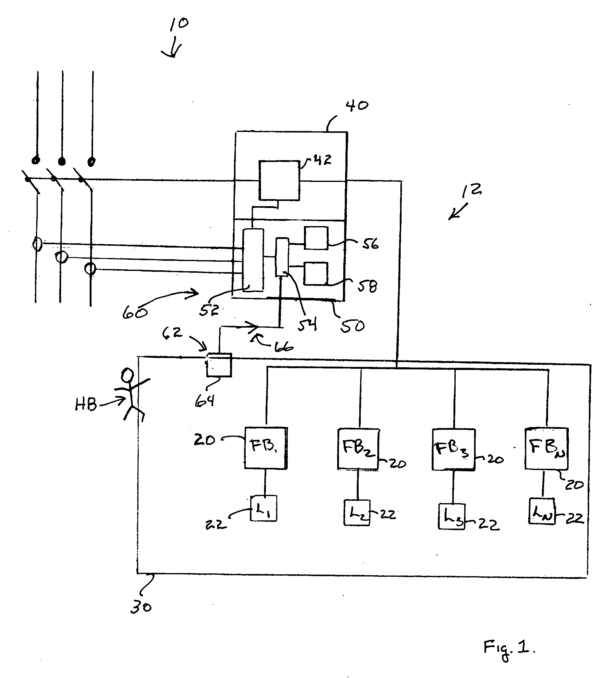
Embodiment Construction

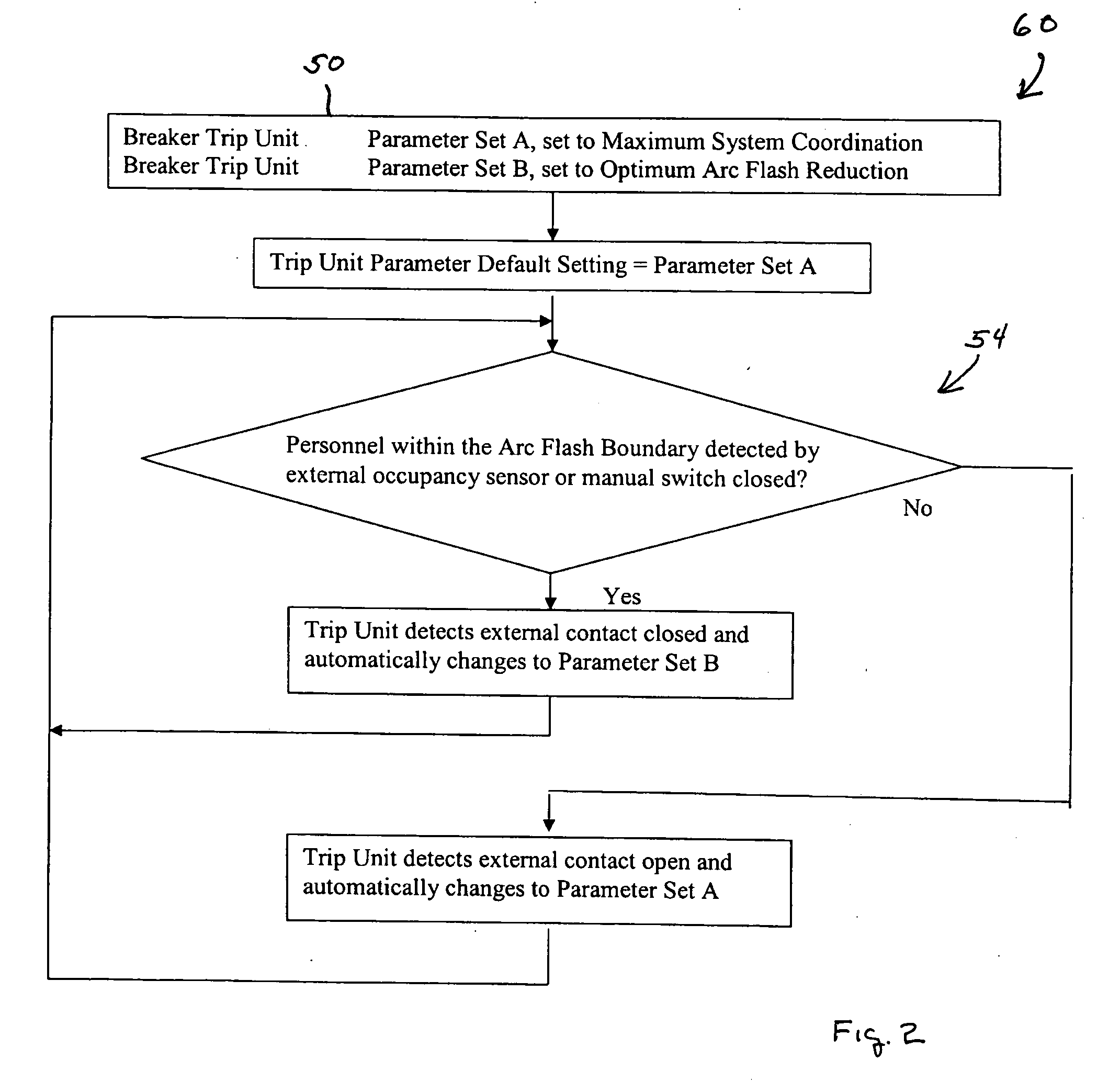
[0012] Before describing an exemplary embodiment of an occupancy-based control device 60 in a main circuit breaker system 12, several comments are appropriate. As mentioned above, high levels of arc flash energy are dangerous to personnel that may be working in the affected area. A publication of the Institute of Electrical and Electronic Engineers (IEEE) Document No. 1584 provides a guide for performing arc flash hazard calculations. It is those calculations that are utilized to set the parameters of the trip unit 50 of the main circuit breaker 40 in response to conditions relating to the main circuit breaker system 12.

[0013] In addition to the use of personal protective equipment (PPE) or opening the main circuit breaker, other methods of reducing arc flash have been used. For example, a ground fault detection system trips the circuit breaker during the lower current stages of fault development and prior to “bolted fault” conditions. The use of finger-safe electrical components c...


PUM


Abstract

A method and occupancy-based control device in a trip unit of a main circuit breaker, with the circuit breaker coupled to an electrical distribution system including at least one feeder circuit breaker and a load circuit. The occupancy-based control device comprises an input device associated with the electrical distribution system and coupled to the trip unit. A selector is coupled to the trip unit and configured to select a first set of parameters and a second set of parameters, with each set of parameters defining a mode of operation of the trip unit. A means for selecting one of the first set of parameters and a second set of parameters in response to a signal from the input device is provided wherein, the trip unit operates based on the selected set of parameters.

Description

FIELD [0001] The present invention relates to circuit breakers and more specifically to a power or main circuit breaker having a trip unit coupled to an occupancy-based control device for monitoring a flash protection boundary. BACKGROUND [0002] In a power or main circuit breaker system within an electric distribution system, a main circuit breaker or power circuit breaker is connected between a power source terminal and a plurality of branch load circuits. Additionally, feeder circuits may be coupled in the electrical distribution system. Typically, each branch or feeder circuit is protected by a circuit breaker or fuse connected between the power source and the load, such as an induction motor or the like. In operation, the main circuit breaker typically is configured to operate, or trip at a higher power setting, current pass through, then the branch circuit breakers or feeder circuit breakers. If a short circuit or other reason to cut power to a specific load circuit occurs, the...

Claims


Application Information

Patent Timeline
IPC IPC(8): H02H3/00
CPCH02H3/006H02H9/008
Inventor CULLIGAN, JOHN LOUISCLARK, RAY MONTGOMERY
Owner SIEMENS ENERGY & AUTOMATION INC
Why Eureka
Try Eureka