
Timepiece with an interchangeable bezel

Active Publication Date: 2006-06-01
THE SWATCH GROUP MANAGEMENT SERVICES
View PDF8 Cites 26 Cited by
  • Summary
  • Abstract
  • Description
  • Claims
  • Application Information

AI Technical Summary

Benefits of technology

[0007] It is thus an object of the present invention to overcome the drawbacks of the prior art by allowing a bezel to be easily replaced by another bezel, via a bayonet device, with precise positioning and without any risk of damaging the assembling means.

Problems solved by technology

In all these resilient assemblies it is difficult to find a good compromise between a device that is sufficiently flexible to allow a user to replace the bezel without any particular effort and a device that is sufficiently secure to prevent it being accidentally lost.
These constructions also have the drawback of being relatively complex and having a certain fragility, particularly when the bayonet device is set in place with a rotational movement of the bezel that is too forced and capable of damaging the assembling elements.

Method used


Image

  • Timepiece with an interchangeable bezel
  • Timepiece with an interchangeable bezel
  • Timepiece with an interchangeable bezel

Examples


case 10

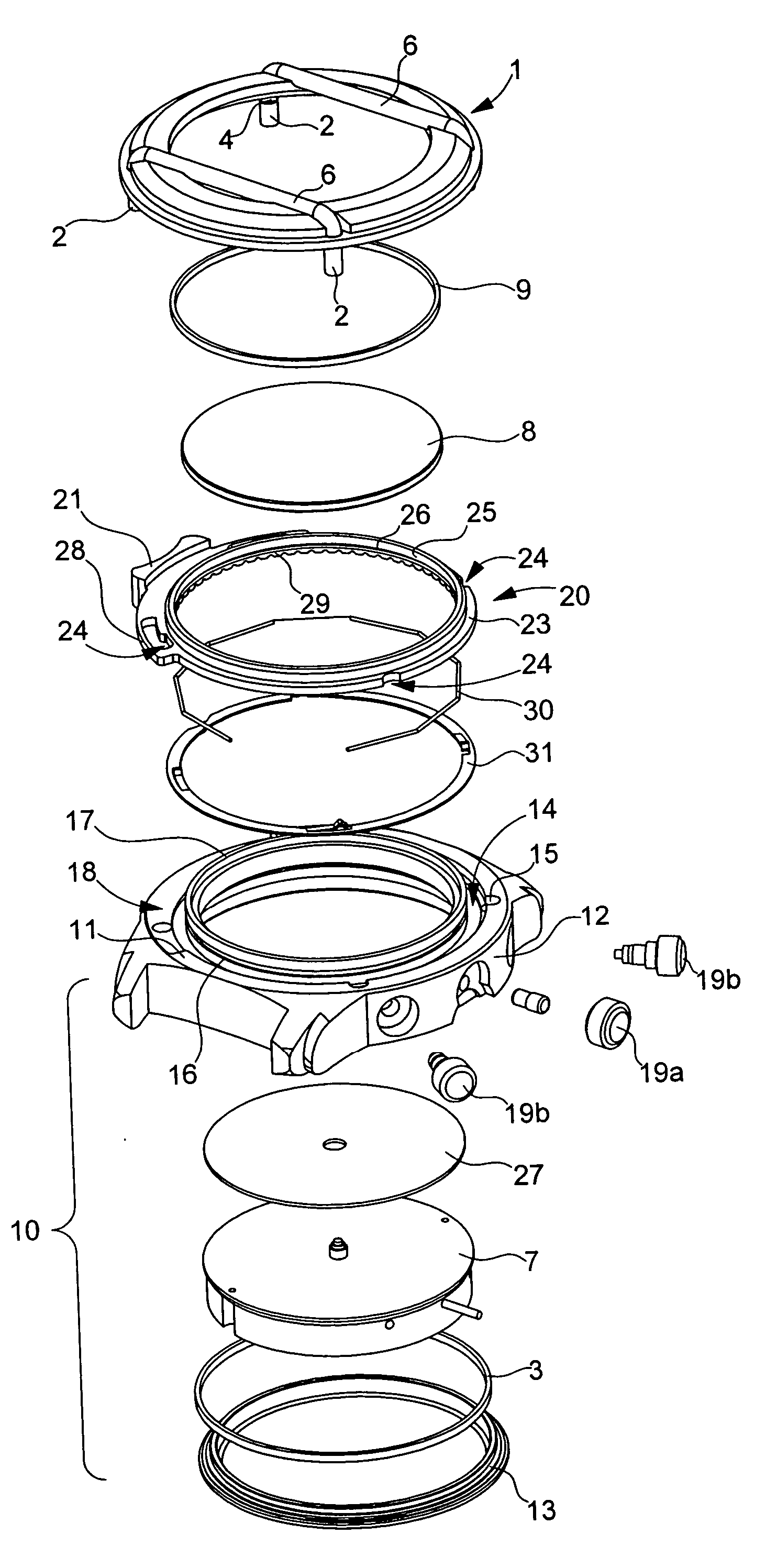
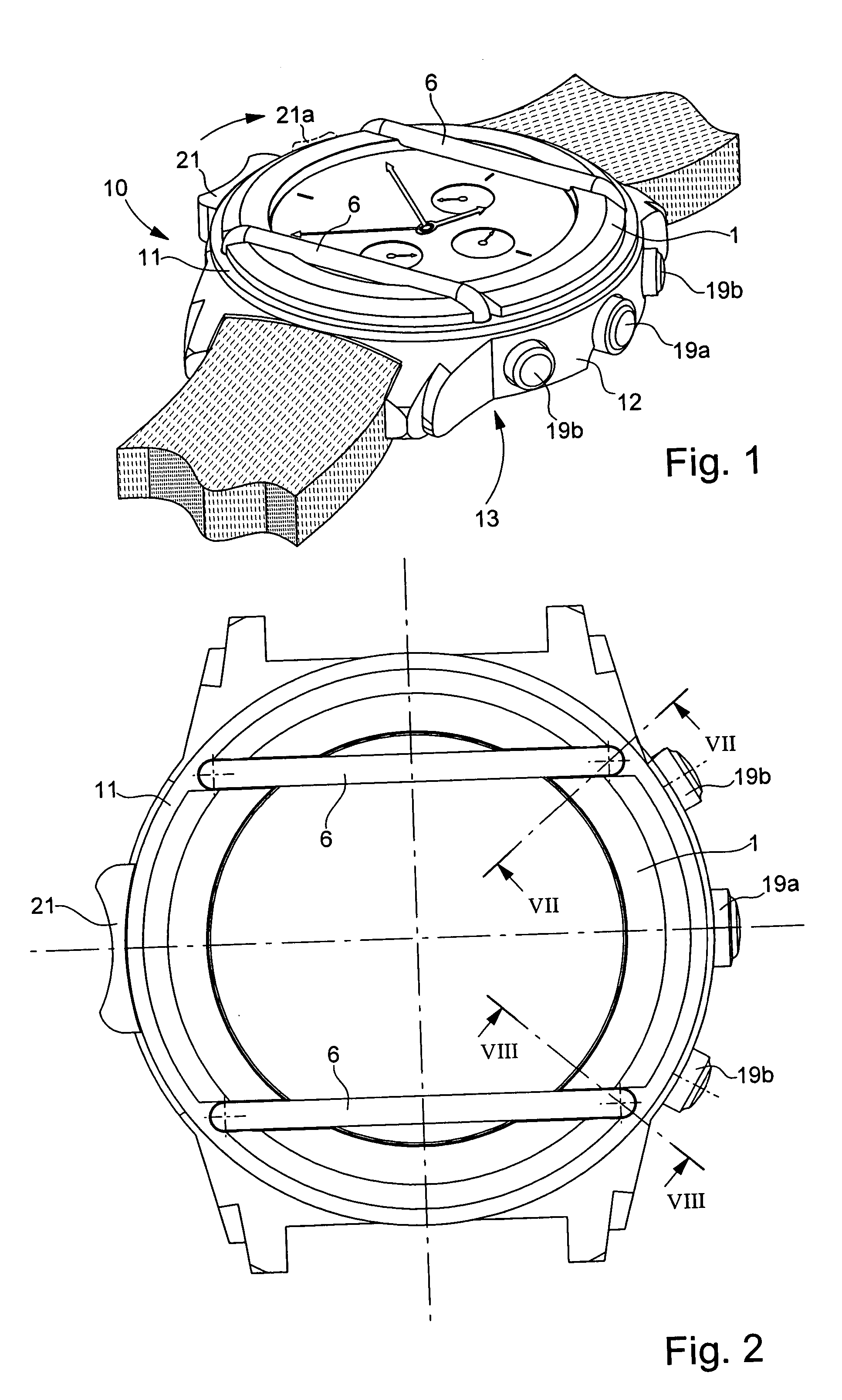
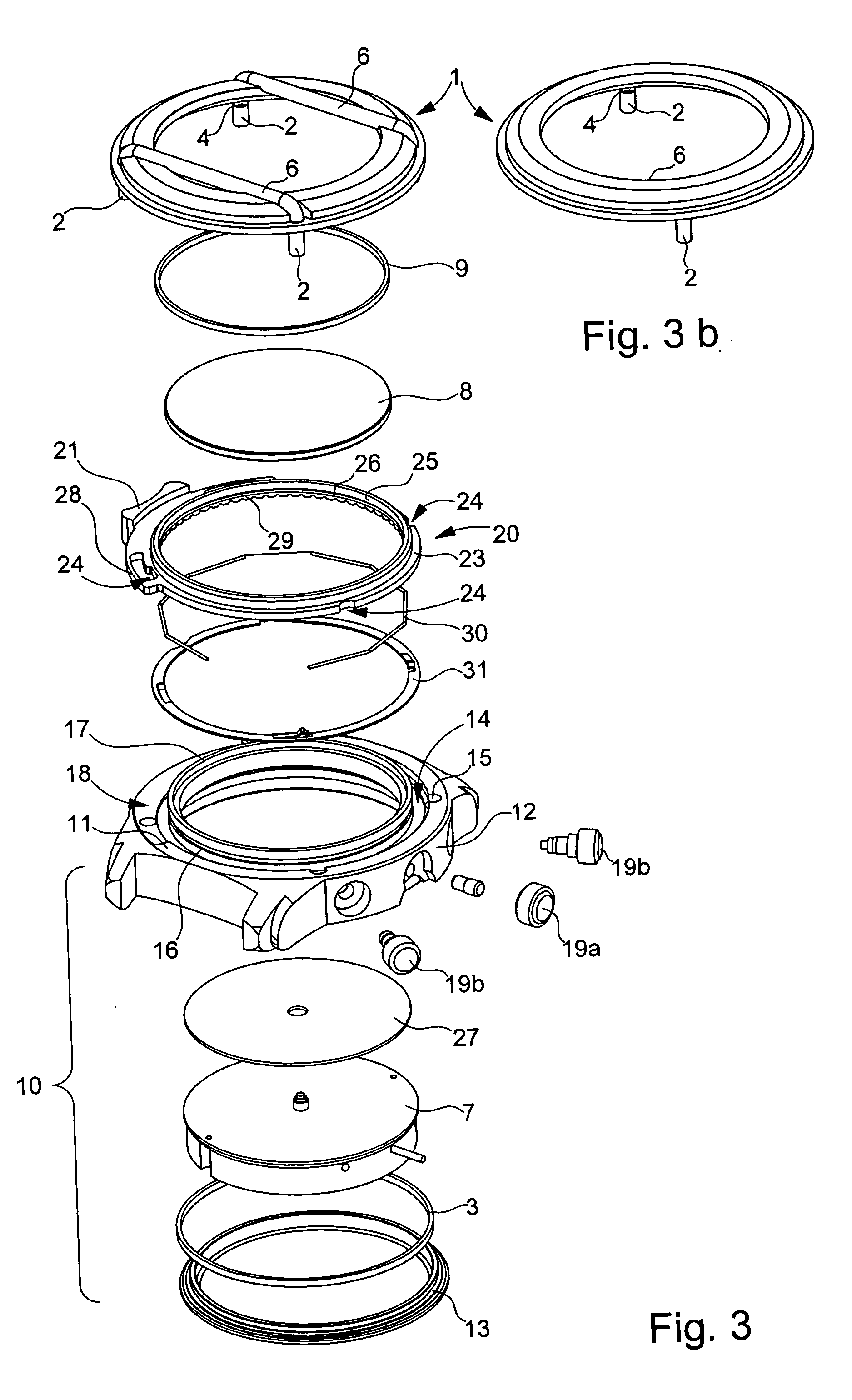
[0028] Case 10 comprises a middle part 12, in which a watch movement 7 and dial 27 are mounted, closed by a back cover 13 with the insertion of a sealing gasket. The upper shoulder 11 of middle part 12 comprises a circular groove 14, whose edge oriented towards the centre of dial 27 is extended by a sleeve 17. Shoulder 11 also comprises four vertical sinks 15 which open out partially into groove 14, i.e. having an aperture that intersects with an edge of groove 14, which is the outer edge in this example. Sleeve 17 of middle part 12 comprises an annular gorge 16 located above shoulder 11. it can also be seen that shoulder 11 has a recess 8 in an angular sector around 9 o'clock to allow manipulation member 21 to pass. Crystal 8 and sealing gasket 9 are obviously fitted onto the middle part flush with sleeve 17.

[0029] Interchangeable bezel 1, shown in FIGS. 3, 3b, 4 and 4b is provided with feet 2, the section of which allows soft engagement in sinks 15 and which are thus distributed a...


PUM


Abstract

The bezel (1) is interchangeable via a bayonet device. The shoulder (11) of the middle part (12) is provided with a circular groove (14) and at least two sinks (15) opening out partially into said groove (14). The bezel (1) includes at least two feet (2) positioned to engage in the sinks (15), said feet (2) each including a notch (4) open radially at the emergence of the sinks (15). A locking ring (20) provided with an outer member (21) for rotational manipulation, is positioned in the groove (14), one edge (23) of said ring (20) having a substantially equal thickness to the aperture of the notches (4) and including recesses (24) for the feet (2) to pass and the other edge (25) including a gorge (26) facing a gorge (16) of the middle part (12), the two gorges (16; 26) housing a click spring (30) of the ring (20).

Description

[0001] This application claims priority from European Patent Application No. 04028072.9 filed Nov. 26, 2004, the entire disclosure of which is incorporated herein by reference. FIELD OF THE INVENTION [0002] The present invention concerns a timepiece, more particularly a wristwatch comprising an interchangeable bezel, i.e. a bezel that can easily be replaced with precise positioning and without any risk of damaging the assembling means. BACKGROUND OF THE INVENTION [0003] A certain number of devices that allow a bezel to be replaced by another for aesthetic or functional reasons, particularly in a wristwatch, are already known. For an aesthetic purpose, this for example allows the colour of the most visible part of the watch to be match with that of clothing, at little cost. For a functional purpose, the replacement of the bezel for example allows the indications carried by said bezel to be altered, or the movement to be acted upon in order to have a multi-function watch. EP Patent No...

Claims


Application Information

Patent Timeline
IPC IPC(8): G04B39/00G04B37/00G04G99/00
CPCG04B19/283G04B45/0092G04B47/046G04B37/18
Inventor GERBER, STEEVE
Owner THE SWATCH GROUP MANAGEMENT SERVICES
Learn More