Indicating regions within a picture

a region and picture technology, applied in the field of video coding, can solve the problems of consuming more bandwidth, encoding of frequent intra frames in the video sequence, and inability to correctly decode frames depending thereon

Active Publication Date: 2006-06-01
NOKIA CORP
View PDF11 Cites 37 Cited by
  • Summary
  • Abstract
  • Description
  • Claims
  • Application Information

AI Technical Summary

Benefits of technology

[0028] In the following, the invention will be described in detail in connection with preferred embodiments with reference to the accompanying drawings, in which
[0029]FIG. 1 shows the conceptual structure of the JVT / H.26L design;
[0030]FIG. 2 shows a preferred embodiment of a growing reliable region;
[0031]FIG. 3 shows an example procedure of adding macroblocks into a reliable region according to a certain refresh pattern;
[0032]FIG. 4 shows a picture to be encoded in relation to macroblocks defined for video encoding;
[0033]FIG. 5 shows a principal drawing of video coding slices formed for the picture of FIG. 4 according to the sub-picture implementation;

Problems solved by technology

If a frame is lost, frames depending thereon can no longer be correctly decoded.
However, as the above-mentioned reference picture selection technique allows referencing to frames prior to an intra frame, an intra frame as such is not a sufficient condition for a random access point.
Furthermore, encoding of frequent intra frames in the video sequence requires more codec processing capacity and consumes more bandwidth.
The decoder can reconstruct intra-coded macroblocks, but inter-coded macroblocks referring to unknown areas in the motion compensation process cannot be reconstructed correctly.
However, this implementation involves several problems.
Thus, reliable areas may be affected by incorrectly reconstructed pixels in neighbouring macroblocks.
This causes an error that will propagate spatio-temporally when the decoding progresses from a frame to another.
A further problem in the process of gradual decoder refresh relates to poor coding efficiency, when indicating the macroblocks belonging to the initial region and the shape and the growth rate of the region.

Method used


Image

  • Indicating regions within a picture
  • Indicating regions within a picture
  • Indicating regions within a picture

Examples


Embodiment Construction

[0036] The invention is applicable to all video coding methods using region-based motion-compensated temporal prediction. The invention is particularly applicable to different low bit rate video codings typically used in limited-band telecommunication systems. These include for instance ITU-T standards H.263 and H.26L (later possibly H.264), which is currently being standardized. In these systems, the invention is applicable for instance in mobile stations, allowing

[0037] The following is an exemplary illustration of the invention using the JVT / H.26L video coding as an example. The JVT / H.26L will be described to a detailed level considered satisfactory for understanding the invention and its preferred embodiments. For a more detailed description of the implementation of JVT / H.26L, a reference is made to the document: Joint Video Team (JVT) of ISO / IEC MPEG and ITU-T VCEG, DRAFT ISO / IEC 14496-10:2002 (E) “JVT Working draft 2, Release 7”.

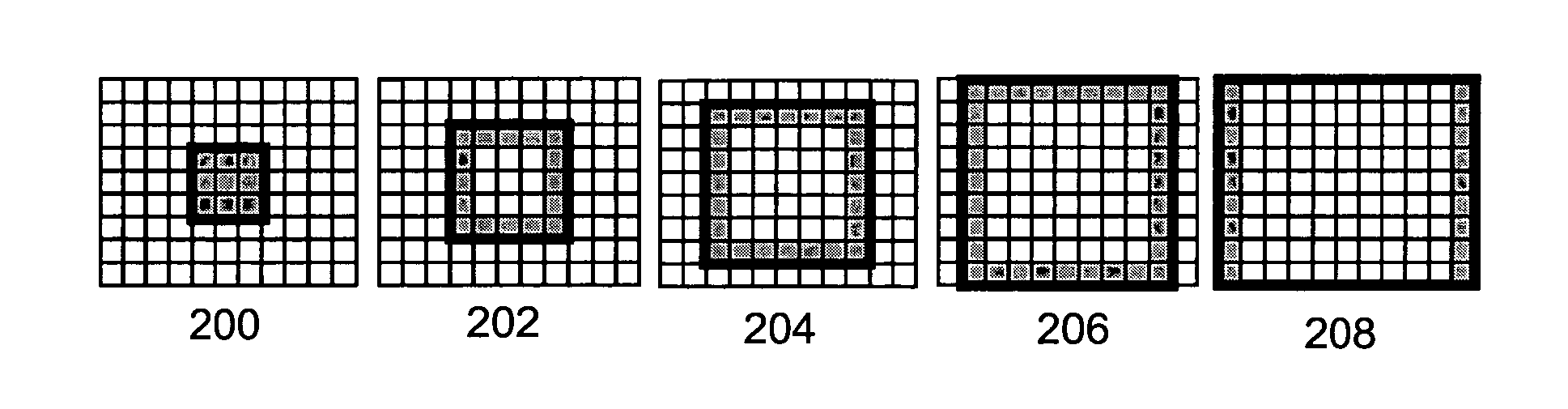
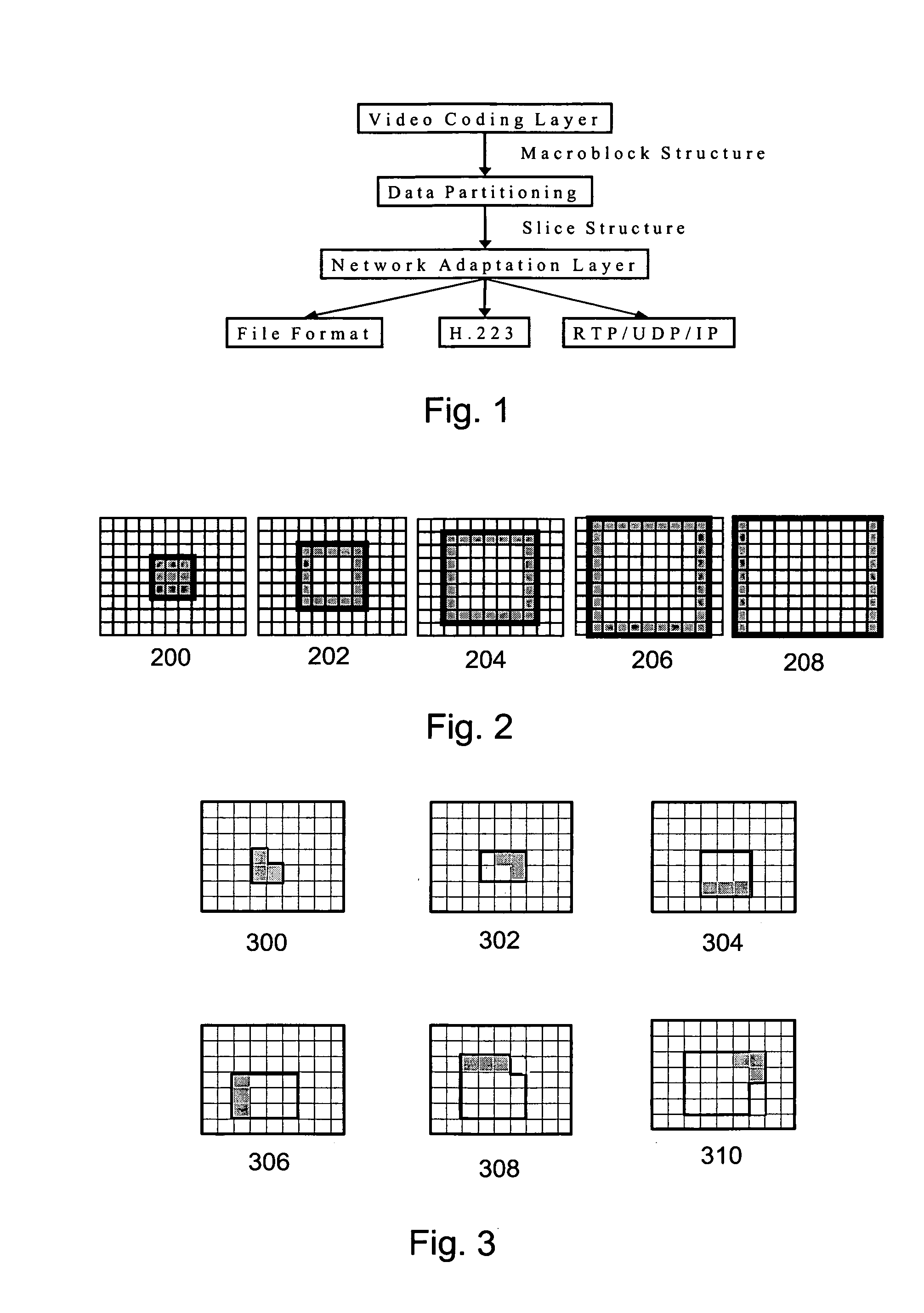
[0038] The conceptual structure of the JVT / H.2...


PUM


Abstract

A method for indicating size, shape and location of a region within a digital picture the picture being divided into a set of blocks. A value for at least one size parameter, which is indicative of a number of the blocks within said region is defined, and a value for at least one shape evolution parameter, which is indicative of a selection order of the blocks in said region is selected. Then preferably the values for said at least one size parameter and said at least one shape evolution parameter are encoded into a bitstream of a video sequence in order to indicate size, shape and location of the region within the picture.

Description

RELATED PATENT DOCUMENTS [0001] This application is a continuation of U.S. patent application Ser. No. 10 / 424,618 filed on Apr. 28, 2003 which is incorporated herein by reference in its entirety.FIELD OF THE INVENTION [0002] The invention relates to video coding, particularly to indicating regions within a picture. BACKGROUND OF THE INVENTION [0003] Video files are composed of a plurality of still image frames, which are shown rapidly in succession as a video sequence (typically 15 to 30 frames per second) to create an idea of a moving image. Image frames typically comprise a plurality of stationary background objects defined by image information that remains substantially the same, and few moving objects defined by image information that changes somewhat. In such a case, the image information comprised by the image frames to be shown in succession is typically very similar, i.e. consecutive image frames comprise much redundancy. More particularly, the redundancy comprised by video ...

Claims


Application Information

Patent Timeline
Patent Type & Authority Applications(United States)
IPC IPC(8): H04N11/04H04N7/12H04B1/66H04N11/02H04N19/50H04N19/176H04N19/89
CPCH04N19/105H04N19/67H04N19/70H04N19/119H04N19/46H04N19/129H04N19/102H04N19/61H04N19/37H04N19/103H04N19/107H04N19/117H04N19/142H04N19/162H04N19/164H04N19/174H04N19/17H04N19/82H04N19/89H04N19/523H04N19/55H04N19/57H04N19/86H04N19/573H04N19/176H04N19/136
Inventor WANG, YE-KUIHANNUKSELA, MISKA
Owner NOKIA CORP
Why Eureka
Try Eureka