Lithium ion polymer multi-cell and method of making

a lithium battery and polymer technology, applied in the field of lithium battery cell configurations, can solve the problems of poor cycle life and calendar life, poor cycle life, poor calendar life,

Inactive Publication Date: 2006-06-01
ENERDEL
View PDF8 Cites 65 Cited by
  • Summary
  • Abstract
  • Description
  • Claims
  • Application Information

AI Technical Summary

Problems solved by technology

Cells with this design show very good discharge rate capability and specific power, but have a poor cycle life and a poor calendar life.
When the cells are laminated at high temperature after formation, i.e., after the initial charging cycle, the cells show very good discharge rate capability and specific power, but again have poor cycle life and poor calendar life caused by cell chemistry deterioration during high temperature cell lamination with the electrolyte.
In a bicell configuration, such as that shown in FIG. 3B, where each bicell includes a positive electrode laminated together with two negative electrodes (or vice versa) in a sandwich-like design and then stacked together to form a battery with N number of bicells, good cycle life and calendar life are achieved due to the lamination process, but only one side of the negative electrodes are used during the discharge process, thereby limiting applicability of the battery for high power or high discharge rate cell applications.

Method used


Image

  • Lithium ion polymer multi-cell and method of making
  • Lithium ion polymer multi-cell and method of making
  • Lithium ion polymer multi-cell and method of making

Examples


Embodiment Construction

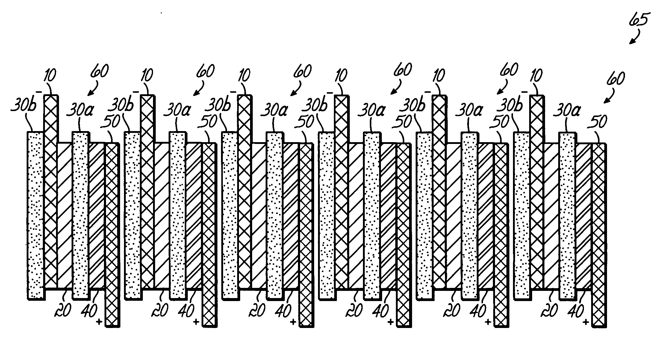
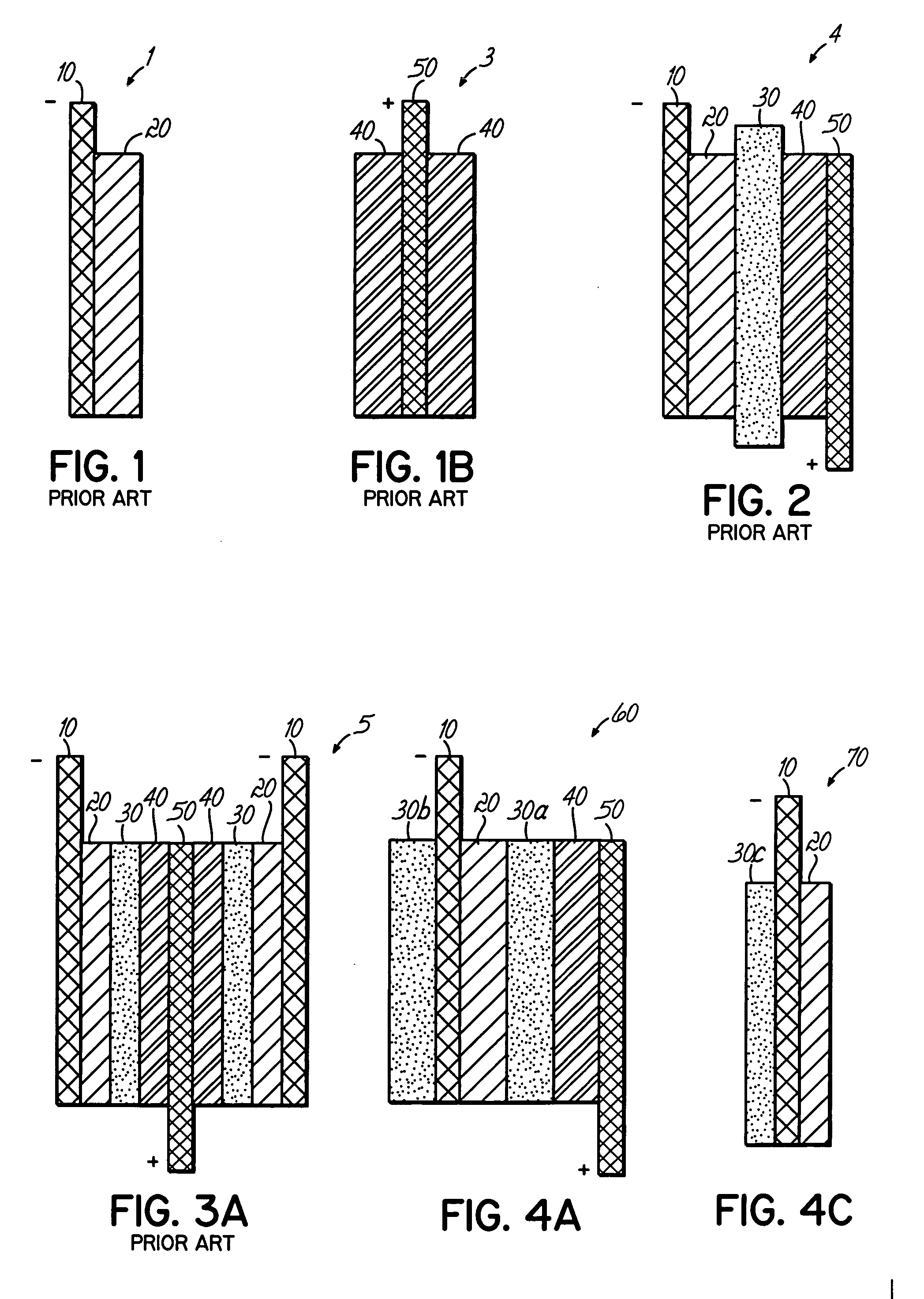
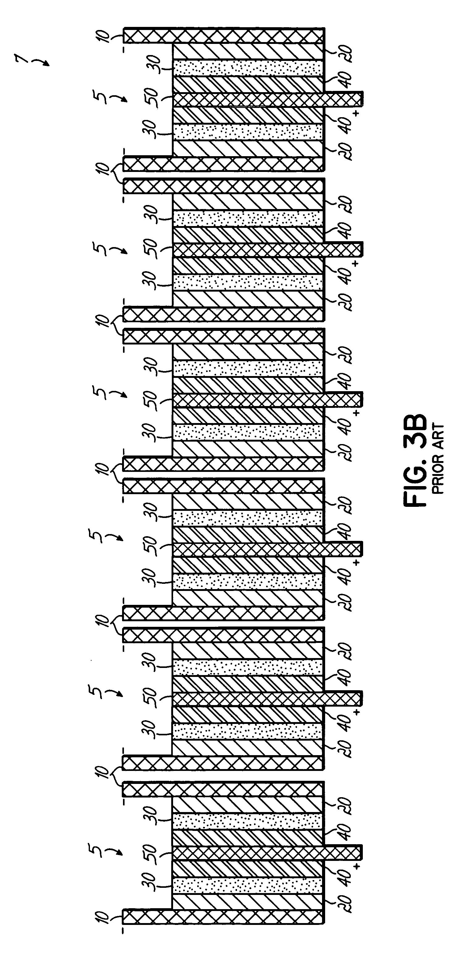
[0025] A battery multi-cell of the present invention comprises a plurality of laminated cell units, ordered in sequence. Each cell unit has a negative electrode (anode) adhered to a negative electrode current collector, a positive electrode (cathode) adhered to a positive electrode current collector, and a first electrolyte-impregnated separator between them. One or both electrode structures (the anode and / or the cathode) may comprise two or more electrode layers that are separated by an internal current collector. For example, an anode structure may be comprised of two negative electrode layers separated by a negative electrode current collector, and / or the cathode structure may be comprised of two positive electrode layers separated by a positive electrode current collector (as shown in FIG 1B). Alternatively, one or both electrode structures (the anode and / or the cathode) may comprise a single electrode layer and a current collector positioned external to the battery cell (as sho...


PUM

PropertyMeasurementUnit
capillary pressureaaaaaaaaaa
pressureaaaaaaaaaa
external energyaaaaaaaaaa

Abstract

A lithium polymer battery or multi-cell and a method of making the multi-cells. The multi-cell comprises a plurality of laminated single cell units, each unit comprising, laminated in sequence, a negative electrode current collector, a negative electrode, a first electrolyte-impregnated separator, a positive electrode, and a positive electrode current collector. These single cell units are stacked one next to another in sequence and a second electrolyte-impregnated separator is positioned between adjacent laminated cell units. The method includes positioning, in sequence, a negative electrode current collector, a negative electrode, a first porous separator, a positive electrode, and a positive electrode current collector to form a single cell unit. A plurality of the single cell units are then positioned adjacent one another in sequence, and a second porous separator is positioned between adjacent single cell units. The method further includes impregnating each of the first and second porous separators with an electrolyte and laminating each single cell unit, but adjacent cell units are not laminated to one another.

Description

TECHNICAL FIELD [0001] This invention relates to cell configurations for multi-cell lithium batteries, in particular lithium ion and lithium ion polymer battery cells, and a method of making multi-cells. BACKROUND OF THE INVENTION [0002] Lithium ion cells and batteries are secondary (i.e., rechargeable) energy storage devices well known in the art. The lithium ion cell, known also as a rocking chair type lithium ion battery, typically comprises essentially a carbonaceous anode (negative electrode) that is capable of intercalating lithium ions, a lithium-retentive cathode (positive electrode) that is also capable of intercalating lithium ions, and a non-aqueous, lithium ion conducting electrolyte therebetween. [0003] The carbon anode comprises any of the various types of carbon (e.g., graphite, coke, carbon fiber, etc.) which are capable of reversibly storing lithium species, and which are bonded to an electrochemically conductive current collector (e.g. copper foil or grid) by means...

Claims


Application Information

Patent Timeline
Patent Type & Authority Applications(United States)
IPC IPC(8): H01M10/04H01M6/46H01M2/14
CPCH01M10/0525H01M10/0565Y10T29/49112Y02E60/122H01M10/0585Y02E60/10Y02P70/50
Inventor PARSIAN, MOHAMMADMANEV, VESSELIN G.CHIA, YEE-HO
Owner ENERDEL
Why Eureka
Try Eureka