Two-stage scar generation for treating atrial fibrillation

a scar generation and atrial fibrillation technology, applied in the field of atrial fibrillation implants, can solve the problems of more aggressive healing responses, increased risk of damage, and significant trauma to the ablated tissue, and achieve the effects of minimizing unwanted tissue damage to patients, reducing the risk of damage, and reliably ablation through the target tissu

Inactive Publication Date: 2006-06-01
SYNTACH AG
View PDF99 Cites 16 Cited by
  • Summary
  • Abstract
  • Description
  • Claims
  • Application Information

AI Technical Summary

Benefits of technology

[0009] It is another object of the present invention to provide an ablation device that more precisely creates scars within target tissue.
[0010] It is yet another object of the present invention to provide an ablation device that minimizes unwanted tissue damage to a patient.
[0011] It is yet another object of the present invention to provide an ablation device that more reliably ablates through a target tissue.
[0012] It is yet another object of the present invention to provide an ablation technique that can better compensate for variations within the target tissue.
[0013] It is another object of the present invention to reduce the different sizes and configurations of devices necessary for different patients.
[0014] One preferred embodiment of the present invention seeks to provide a mechanical implant configured to utilize at least two different scar-generating mechanisms that are generated in sequential or overlapping stages. For example, the present invention provides an expandable device that can be positioned at a desired target location within a patient to generate mechanical ablation damage. After a predetermined amount of mechanical ablation has occurred, additional ablation damage is generated by a different source, such as RF, drug delivery, or material delivery. In this respect, the overall ablation scarring can be better controlled by utilizing the ablation techniques that are most appropriate at specific phases of a technique or locations within a patient.

Problems solved by technology

For example, while RF energy ablation adequately ablates the target tissue, it can also easily char the surface tissue or cause the water in the tissue to boil, causing significant trauma to the ablated tissue.
This damage becomes more likely as the depth of the burn increases and can result in more aggressive healing responses at the ablation site.
Furthermore, this aggressive healing response can become a clinical problem if it occurs in and causes narrowing of the pulmonary veins.
For example, it can be difficult with scar generating material to create a deep scar within tissue without accommodating for migration of the drug or material into undesired areas (e.g., adjacent structures or the blood stream).

Method used


Image

  • Two-stage scar generation for treating atrial fibrillation
  • Two-stage scar generation for treating atrial fibrillation
  • Two-stage scar generation for treating atrial fibrillation

Examples


Embodiment Construction

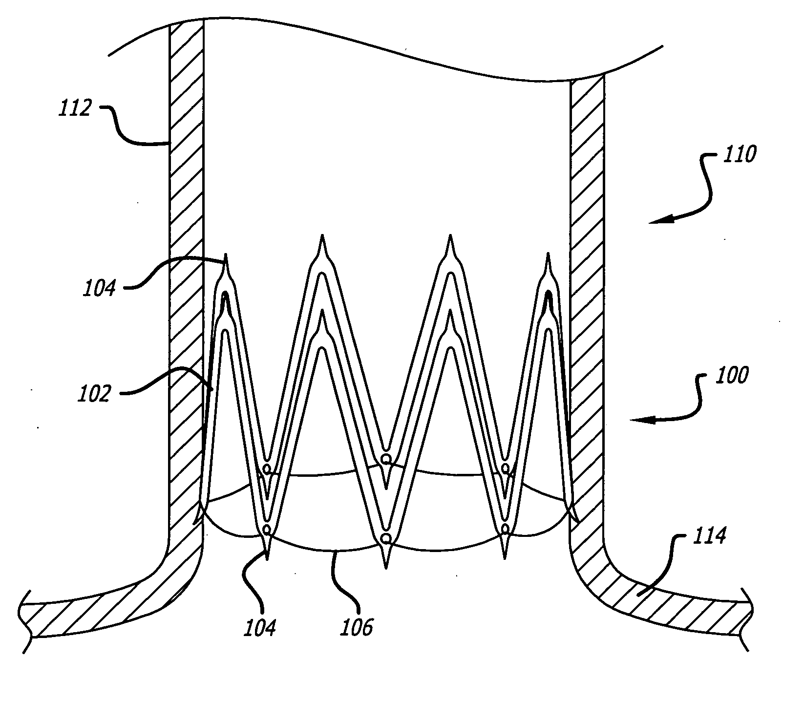
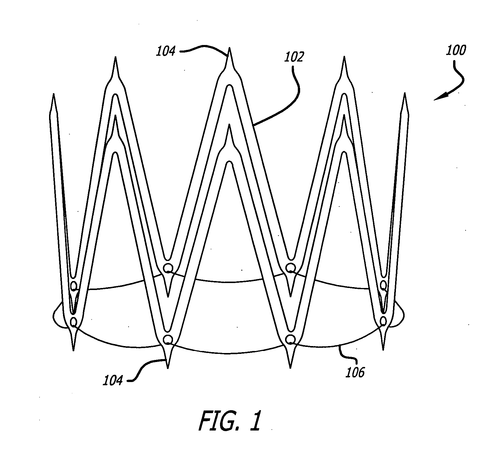
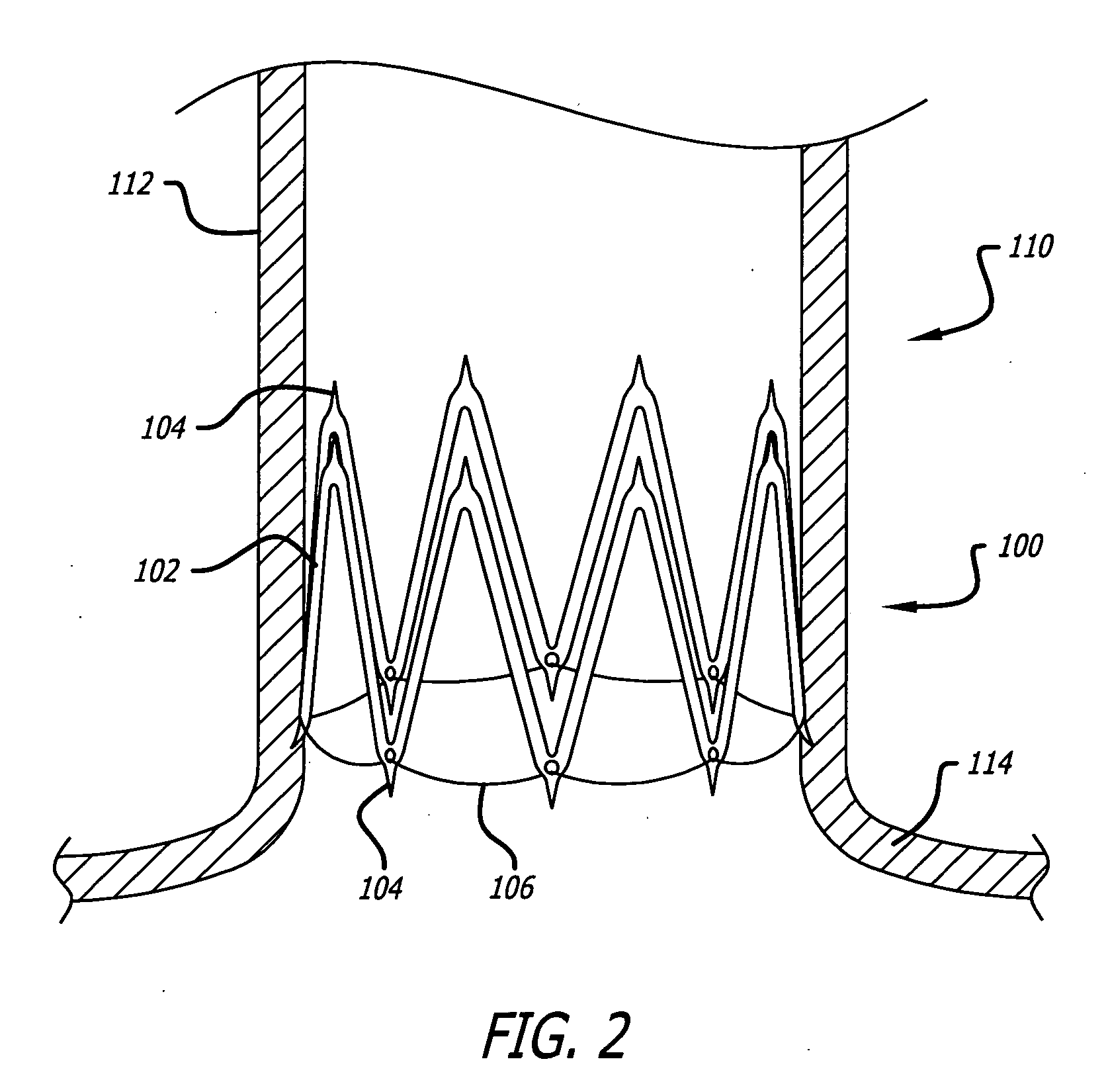
[0023] Generally, the present invention provides a method and apparatus (also referred to as a prosthesis or implant in this specification) to more precisely create an electrical-blocking scar that reduces or eliminates atrial fibrillation. More specifically, the invention improves the precision of the scar creation and reduces the negative side effects of the previously known ablation techniques. It does this by utilizing a combination of multiple ablation techniques. Since different single ablation techniques have different advantages and disadvantages, multiple techniques can be used in sequence or in an overlapping manner to maximize their advantages and minimize their drawbacks. Thus, with the present invention, a more precise scar can be reliably created to block electrical signals from otherwise propagating through target tissue.

[0024] For example, in one embodiment, a mechanical force caused by a prosthesis or implant may be initially used to generate scarring through a por...


PUM


Abstract

The present invention seeks to provide an implant configured to utilize at least two different scar-generating mechanisms that are generated in sequential or overlapping stages. For example, in one embodiment the present invention provides an expandable device that can be positioned at a desired target location within a patient to generate mechanical ablation damage. After a predetermined amount of mechanical ablation has occurred, additional ablation damage is generated by a different source, such as energy delivery, drug delivery, or inflammatory material delivery. In this respect, the overall ablation scarring can be better controlled by utilizing the ablation techniques that are most appropriate at specific phases of a technique or locations within a patient.

Description

RELATED APPLICATIONS [0001] This application claims priority to U.S. Provisional Application Ser. No. 60 / 617,260 filed Oct. 8, 2004 entitled Implant To Drive Two-Stage Scar Generation In Pulmonary Veins And Left Atrium For Treating Atrial Fibrillation; and U.S. Provisional Application Ser. No. 60 / 664,925 filed Mar. 24, 2005 entitled Two-Stage Ablation Of Tissue Around Pulmonary Veins To Treat Atrial Fibrillation; the contents of which are hereby incorporated by reference.BACKGROUND OF THE INVENTION [0002] This invention is related to implants used to treat atrial fibrillation. Typically, these implants are used to create a scar line through the wall of the ostium of the pulmonary veins or of the atrial wall just inside the atrium from the pulmonary veins. If properly positioned, these scars have the effect of blocking electrical conduction through the tissue of the wall. Blocking this electrical conduction, particularly around the ostia of the pulmonary veins, is known to be effecti...

Claims


Application Information

Patent Timeline
Patent Type & Authority Applications(United States)
IPC IPC(8): A61B17/00A61B18/18
CPCA61B17/08A61B17/12A61B18/14A61B2017/00243A61B2017/081A61B2018/00375A61B18/18
Inventor CORNELIUS, RICHARDSWANSON, WILLIAMSULLIVAN, DANIELSHEBUSKI, RONALD
Owner SYNTACH AG
Why Eureka
Try Eureka