Vacuum cleaner and dust collection unit thereof

a vacuum cleaner and dust collection technology, applied in the field of vacuum cleaners, can solve the problems of user's body down, user's dissatisfaction, user's dust collection, etc., and achieve the effects of convenient separation, convenient separation, and improved appearan

Active Publication Date: 2006-06-08
LG ELECTRONICS INC
View PDF5 Cites 24 Cited by
  • Summary
  • Abstract
  • Description
  • Claims
  • Application Information

AI Technical Summary

Benefits of technology

[0010] An object of the invention is to provide a vacuum cleaner and a dust collection unit thereof that allow a user to handle it conveniently.
[0011] Another object of the invention is to provide a vacuum cleaner and a dust collection unit thereof that allow a user to conveniently separate or install it from / at a body of the vacuum cleaner with holding the dust collection unit.
[0012] A further object of the invention is to provide a vacuum cleaner and a dust collection unit thereof that allow a user to more conveniently separate an upper cover of the dust collection unit.
[0013] Further another object of the invention is to provide a vacuum cleaner and a dust collection unit thereof having a more improved appearance by getting rid of portions protruded outward from the dust collection unit.
[0018] According to the present invention, a user can handle the dust collection unit more conveniently from the body. Also, the separation operation of dirt from the dust collection unit can be made simple and convenient. In addition, since the dirt captured on the filter is not detached while the foreign particles are discarded, it is possible to use the dust collection unit more delightfully.

Problems solved by technology

However, to pull out the dust collection unit holding the dust collection box handle, it is disadvantageous that a user has to hold the dust collection box handle using one hand and to operate a hanging structure using the other hand.
Also, since the dust collection box handle is formed in a vertical direction, it is disadvantageous that the user has to hold the dust collection box hand with the user's body down.
Of course, the detached dirt causes a user to feel displeasure.
Furthermore, since the whole of the cover is not pulled out exactly upward, it is disadvantageous that the upper cover and the dust collection box are interfered with each other and are not easily pulled out.

Method used


Image

  • Vacuum cleaner and dust collection unit thereof
  • Vacuum cleaner and dust collection unit thereof
  • Vacuum cleaner and dust collection unit thereof

Examples


Embodiment Construction

[0027] Reference will now be made in detail to the preferred embodiments of the present invention, examples of which are illustrated in the accompanying drawings.

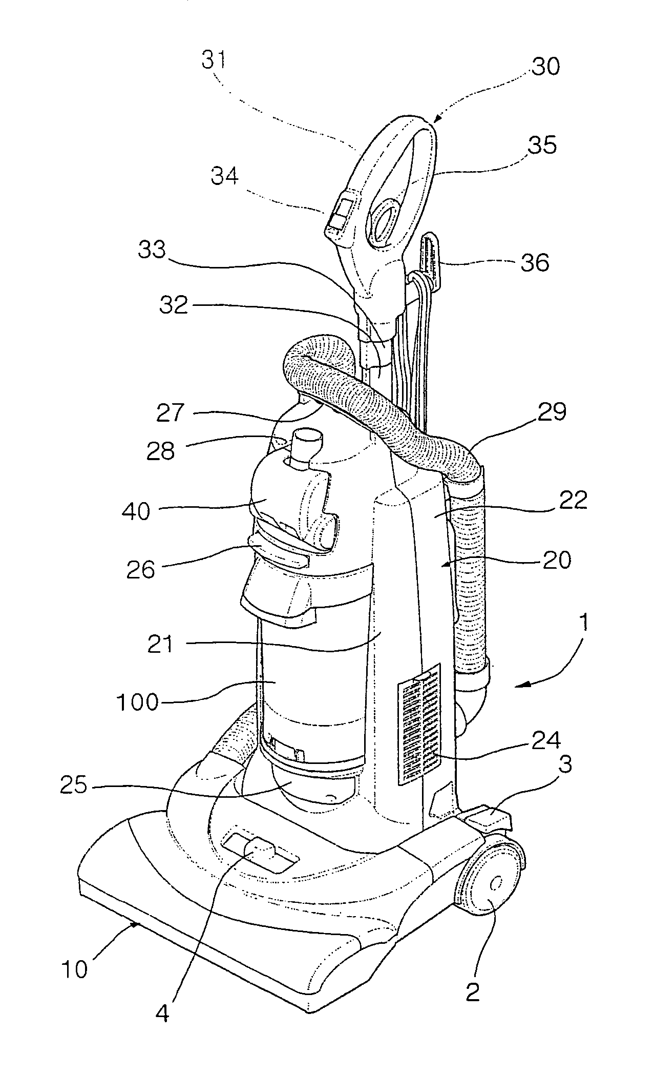
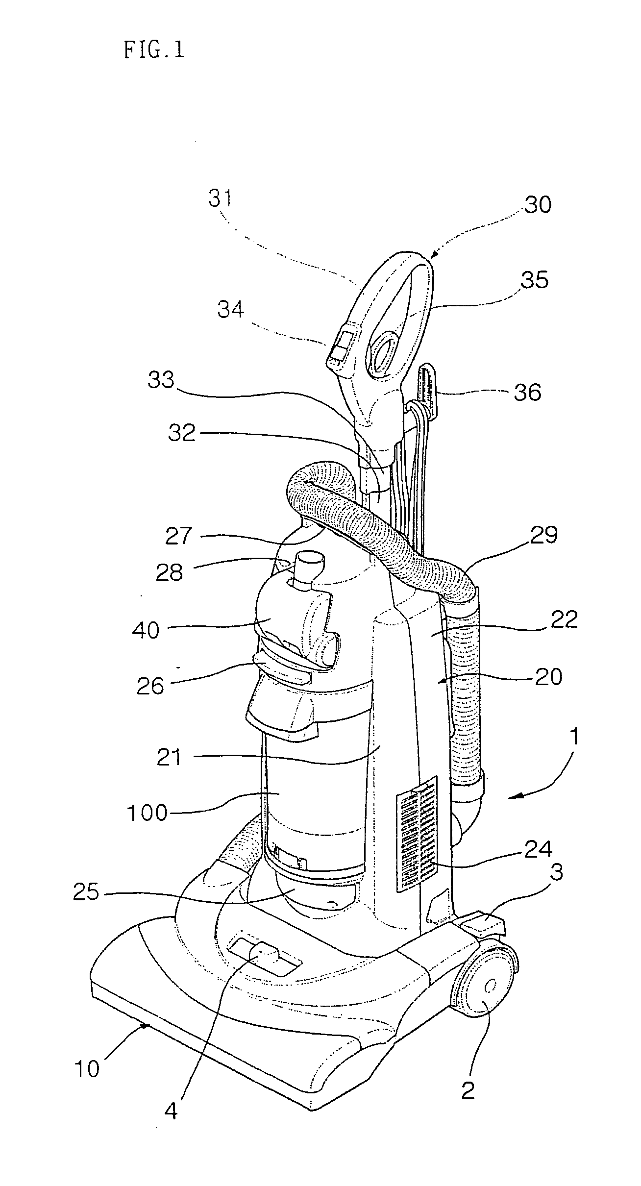
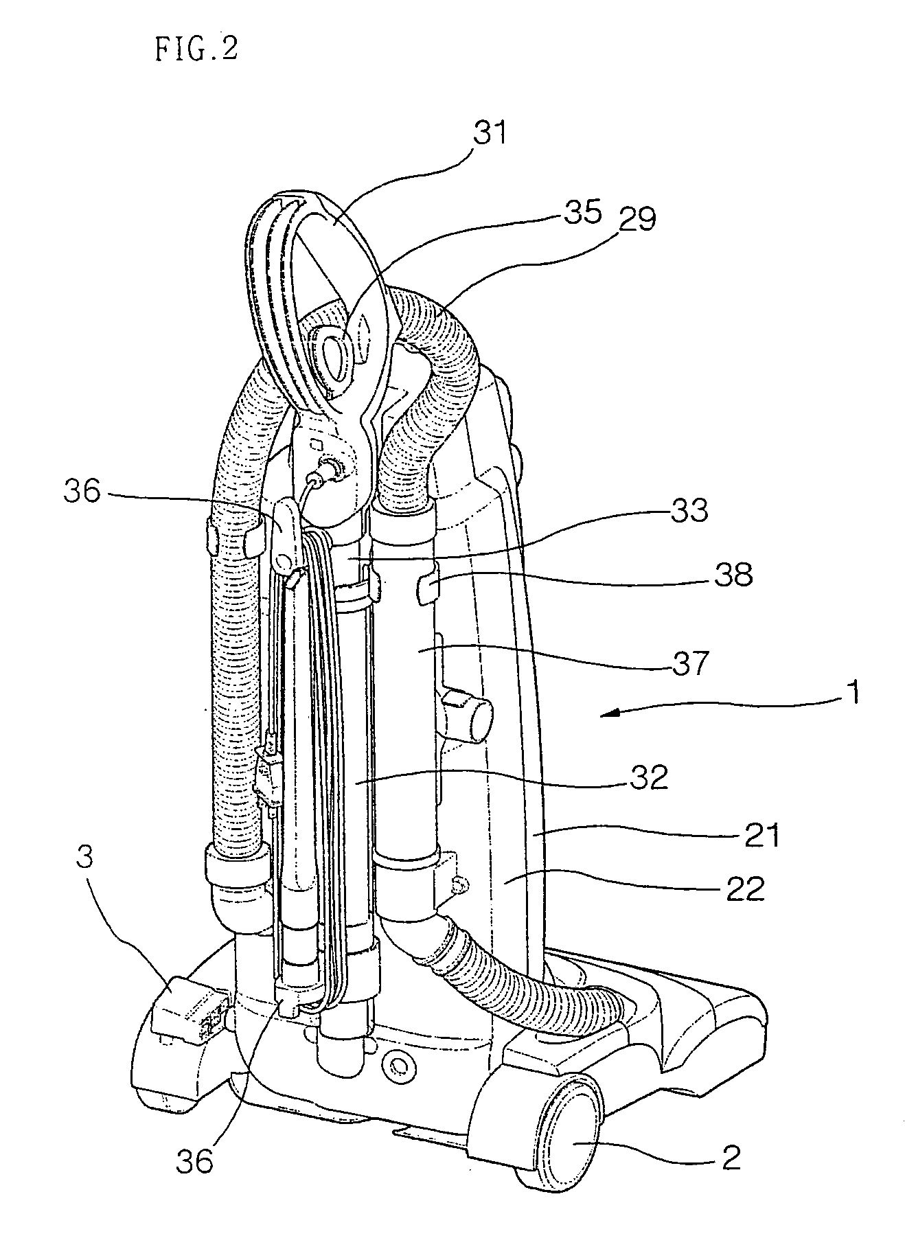
[0028]FIG. 1 is a front perspective view of an upright vacuum cleaner according to the present invention, and FIG. 2 is a rear perspective view of the upright vacuum.

[0029] Referring to FIGS. 1 and 2, the upright vacuum cleaner 1 macroscopically includes a suction nozzle unit 10 contacts with a floor to suck outer air, a body 20 in which main parts including a suction motor and a fan are mounted, and a manipulation handle 30 formed on an upper portion of the vacuum cleaner such that the vacuum cleaner is moved in an easy way during the cleaning work. The cleaning work using the vacuum cleaner is conducted as follows. First, air is sucked through the suction nozzle unit 10 together with foreign particles. The foreign particles are separated from the sucked air while passing through the body 20 and cleaned, and then the cle...


PUM


Abstract

Provided is a dust collection unit of a vacuum cleaner having a handle formed on an outer circumference of the dust collection container and having an opened bottom such that user's fingers are inserted upward from a lower side of the handle for more convenient use of the vacuum cleaner.

Description

BACKGROUND OF THE INVENTION [0001] 1. Field of the Invention [0002] The present invention relates to a vacuum cleaner, and particularly to a dust collection unit of a vacuum cleaner allowing a user to handle it conveniently. Further, the invention relates to a dust collection unit of a vacuum cleaner allowing a user to separate, install and clean it conveniently. [0003] 2. Description of the Related Art [0004] A vacuum cleaner is generally classified into a canister vacuum cleaner and an upright vacuum cleaner. Particularly, the upright vacuum cleaner includes a main body, a nozzle unit and a handle that are integrally formed, so the vacuum cleaner itself is moved when a user pushes or pulls a handle with gripping it. At this time, dusts on the floor are sucked through the nozzle to clean the floor. A general configuration of such an upright vacuum cleaner is already well known from many documents, so its detail description is omitted. [0005] Meanwhile, a dust collection unit is det...

Claims


Application Information

Patent Timeline
Patent Type & Authority Applications(United States)
IPC IPC(8): A47L9/16
CPCA47L9/1666A47L9/1683A47L9/1691A47L9/106
Inventor CHOI, JONG SEONG
Owner LG ELECTRONICS INC
Why Eureka
Try Eureka