Estimating device for exhaust temperature in internal combustion engine

a technology of exhaust temperature and estimating device, which is applied in the direction of electrical control, process and machine control, instruments, etc., can solve the problems of increasing cost and estimating exhaust temperature with accuracy, and achieve the effect of increasing cos

Active Publication Date: 2006-06-08
DENSO CORP
View PDF13 Cites 52 Cited by
  • Summary
  • Abstract
  • Description
  • Claims
  • Application Information

AI Technical Summary

Benefits of technology

[0006] It is a major object of the present invention to provide an estimating device for exhaust temperature in an internal combustion engine wherein the exhaust temperature can be estimated with accuracy without inviting problems, such as increase in cost.

Problems solved by technology

As a result, the exhaust temperature can be estimated with accuracy without inviting such a problem as increase in cost due to the addition of a sensor or the like.

Method used


Image

  • Estimating device for exhaust temperature in internal combustion engine
  • Estimating device for exhaust temperature in internal combustion engine
  • Estimating device for exhaust temperature in internal combustion engine

Examples


Embodiment Construction

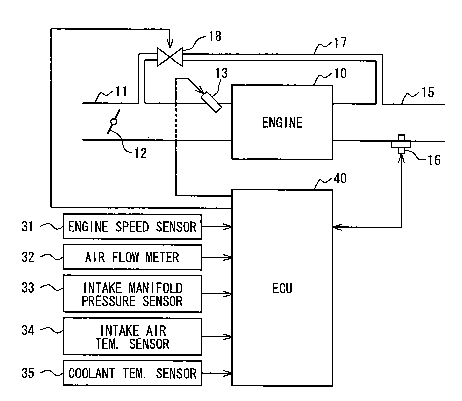
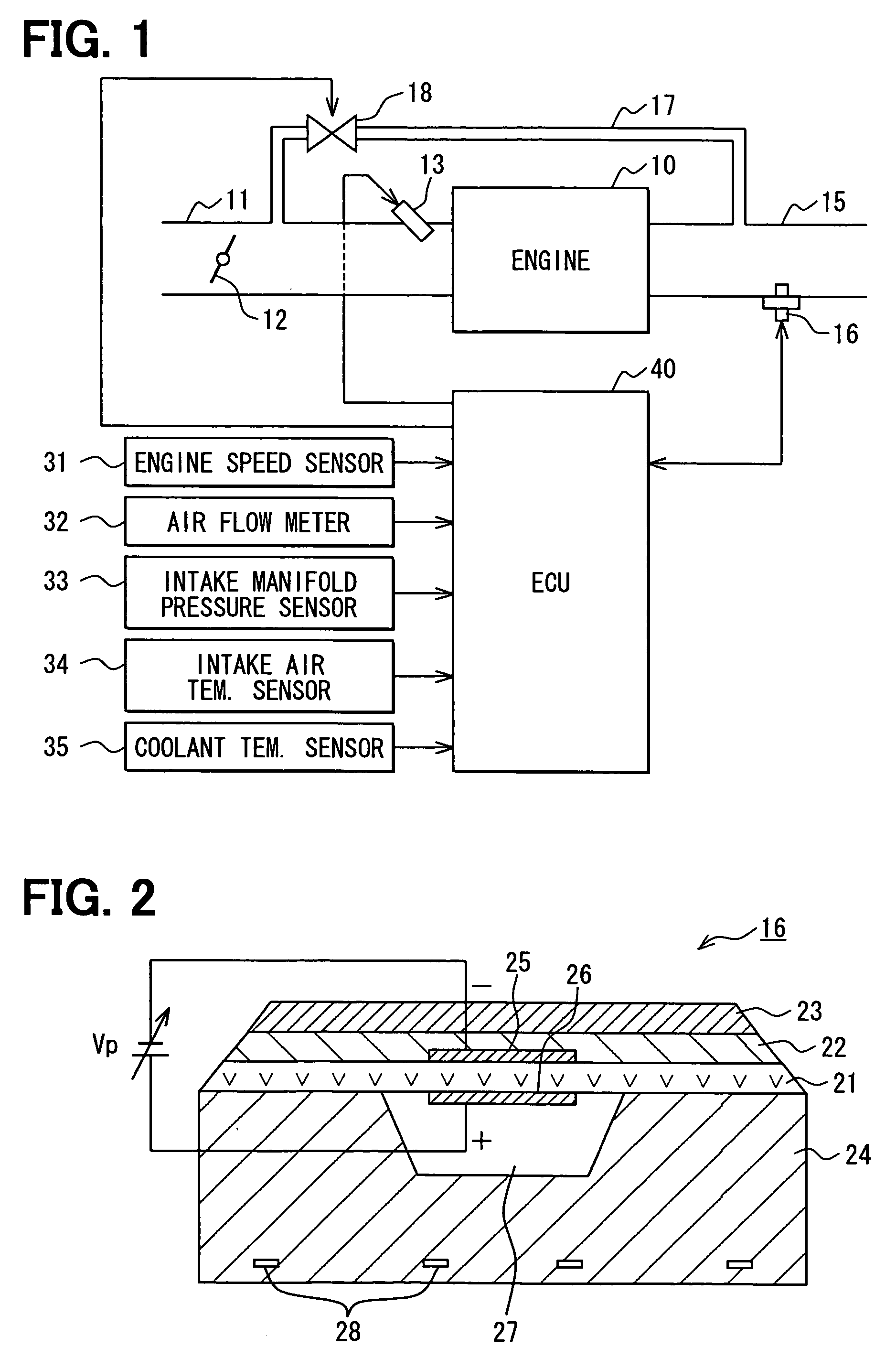
[0060] Hereafter, description will be given to an embodiment in which the present invention is incarnated with reference to the drawings. FIG. 1 is a schematic diagram illustrating the outline of an engine control system. In FIG. 1, an engine 10 is a multi-cylinder gasoline engine. Its intake pipe 11 is provided with a throttle valve 12, and an injector 13 is provided in proximity to an intake port on the downstream side thereof. When fuel is injected from the injector 13, an air-fuel mixture is formed of the injected fuel and air. The air-fuel mixture is burned in the combustion chamber of the engine, and then exhaust is discharged to an exhaust pipe 15. An A / F (Air / Fuel) sensor 16 for detecting an air-fuel ratio is installed in the exhaust pipe 15. As an EGR (Exhaust Gas Recirculation) unit, an EGR passage 17 is provided to connect the intake pipe 11 and the exhaust pipe 15, and an EGR valve 18 is provided at a certain midpoint in the EGR passage 17.

[0061] Here, description will ...


PUM


Abstract

An intake pipe of an engine has an injector, while an exhaust pipe has an A / F (air / fuel) sensor that contains a heater. An ECU detects an element impedance of the air / fuel sensor, and computes an emitted heat quantity of the A / F sensor based on the detected element impedance. The ECU further controls energization of the heater of the A / F sensor and computes a heater release quantity associated with the energization of the heater. Furthermore, the ECU estimates exhaust temperature from a balance between the emitted heat quantity of the A / F sensor and the heater heat release quantity by using at least one of an emitted heat quantity-related parameter and a heat release quantity-related parameter. These two parameters can be calibrated.

Description

CROSS REFERENCE TO RELATED APPLICATIONS [0001] This application is based on and incorporates herein by reference Japanese Patent Application No. 2004-352393 filed on Dec. 6, 2004. FIELD OF THE INVENTION [0002] The present invention relates to an estimating device for exhaust temperature in an internal combustion engine. BACKGROUND OF THE INVENTION [0003] In an internal combustion engine, the exhaust temperature changes according to the operating state of the engine or the like. When this exhaust temperature is learned, it can be incorporated into varied control and the like. To do this, a temperature sensor for exhaust temperature detection can be simply installed. However, this will lead to increased cost. To cope with this, various techniques to estimate the exhaust temperature have been proposed. For example, the exhaust temperature measuring instrument disclosed in Patent Document 1 is so constructed as to estimate the exhaust temperature as follows: its air to fuel ratio sensor...

Claims


Application Information

Patent Timeline
Patent Type & Authority Applications(United States)
IPC IPC(8): F01N3/00F01N5/02F02M25/07F02D41/00G06F17/00
CPCF02D41/0072F02D41/1446F02D41/1447F02D41/1494F02D41/221Y02T10/47Y02T10/40
Inventor OHSAKI, SATORU
Owner DENSO CORP
Why Eureka
Try Eureka