Common rail fuel injection system

a fuel injection system and common rail technology, applied in the direction of fuel injection pumps, liquid fuel feeders, machines/engines, etc., can solve the problems of sudden change of combustion noise, torque shock and rotational fluctuation in the engine that drives the supply pump, deterioration of drivability, etc., and achieve the effect of arbitrarily increasing the fuel injection pressur

Inactive Publication Date: 2006-06-08
MITSUBISHI FUSO TRUCK AND BUS CORPORATION
View PDF9 Cites 3 Cited by
  • Summary
  • Abstract
  • Description
  • Claims
  • Application Information

AI Technical Summary

Benefits of technology

[0009] An aspect of the present invention is a common rail fuel injection system that comprises a common rail that stores fuel pressurized by a pressurizing pump; fuel injection valves that inject the fuel stored in the common rail into respective cylinders of an engine; and a pressure-increase mechanism for introducing the fuel from the common rail to drive an increase-pressure piston and further pressurizing the fuel from the common rail so that fuel injection pressure can be arbitrarily increased, wherein the common rail fuel injection system further comprises a control means for gradually changing the quantity of fuel discharged from the pressurizing pump when at least one of activation and deactivation of the pressure-increase mechanism is carried out.

Problems solved by technology

As a result, there is the problem that as shown in FIG. 13, when the amount of pressurized fuel consumed is abruptly changed in response to activation and deactivation of the pressure-increase mechanism, the quantity of fuel discharged from the supply pump (driving load) is abruptly changed, causing torque shock and rotational fluctuation to occur in an engine that drives the supply pump and therefore deteriorating drivability.
Also, the engine has a property of changing the state of combustion and thereby changing combustion noise depending on fuel injection pressure, and therefore when the target injection pressure is abruptly changed in response to depression of the accelerator pedal or the like, combustion noise is also abruptly changed, causing a driver to feel something is wrong.

Method used


Image

  • Common rail fuel injection system
  • Common rail fuel injection system
  • Common rail fuel injection system

Examples


first embodiment

[0024] A description will now be given of a common rail fuel injection system of an engine for a vehicle according to the present invention.

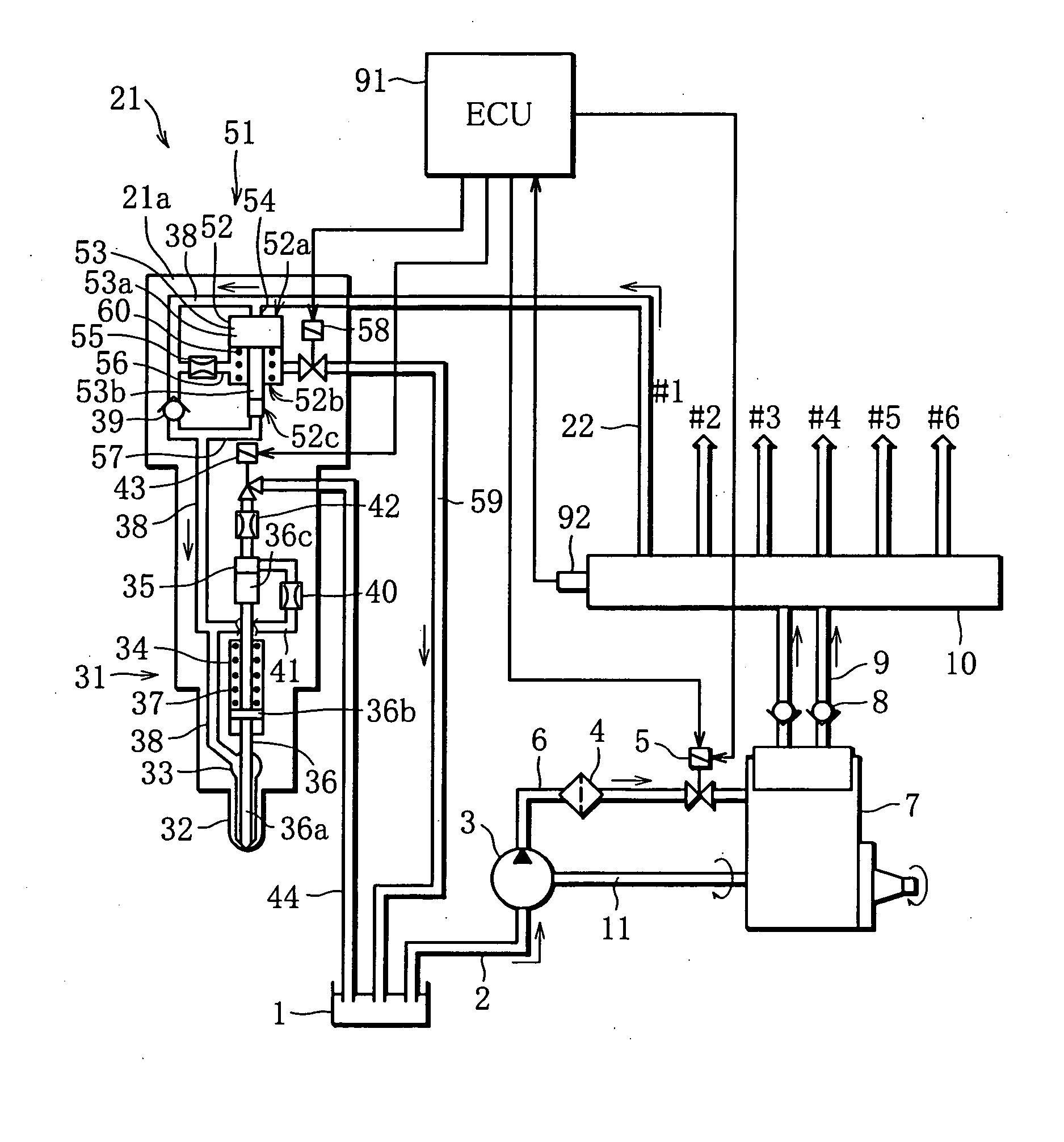
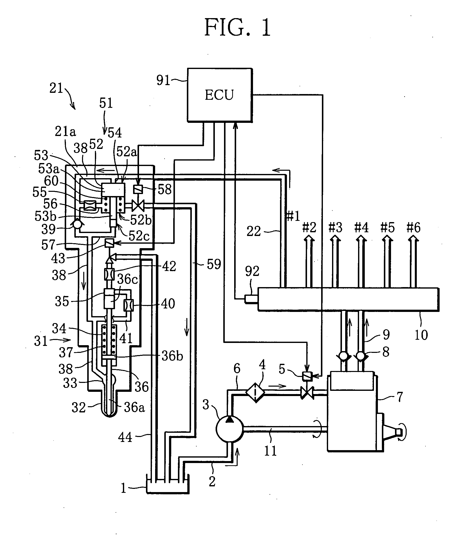
[0025]FIG. 1 is a diagram showing the overall construction of the common rail fuel injection system according to the first embodiment. A fuel tank 1 disposed in a vehicle is connected to a feed pump 3 via a tank fuel passage 2. The feed pump 3 is connected to a supply pump 7 (pressurizing pump), which is provided with a filter 4 and an electromagnetic fuel supply amount adjusting valve 5, via a fuel feed passage 6. The supply pump 7 is connected to a common rail 10 via a pair of fuel supply passages 9 provided with respective check valves 8. In FIG. 1, the feed pump 3 and the supply pump 7 are separated from each other, but in actuality, the pumps 3 and 7 are configured as an integral unit and driven by an engine, not shown, via a common drive shaft 11.

[0026] Fuel in the fuel tank 1 is pumped up by the feed pump 3 and supplied to the supply pum...

third embodiment

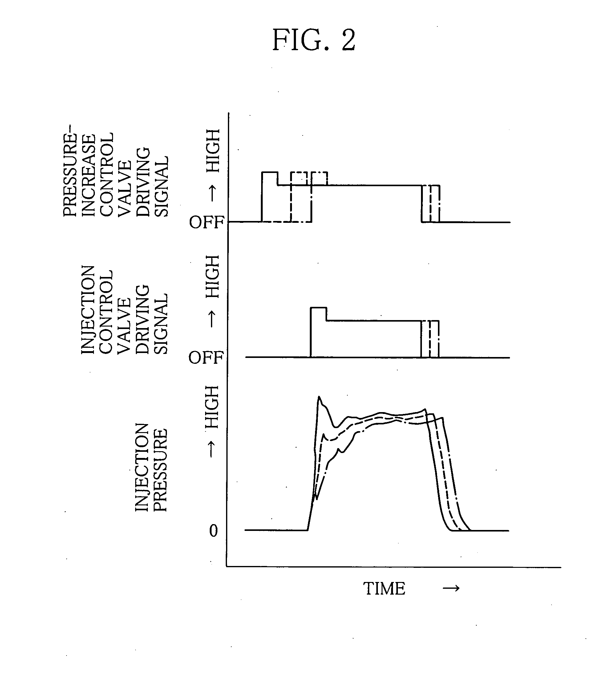
[0073]FIG. 11 is a time chart showing how fuel pressure is increased for fuel injection during the pressure-increase timing control. It should be noted that how the pressure-increase timing control is carried out is identical with how the pressure-increase time period control in the third embodiment described above and illustrated in FIG. 9, and description thereof is therefore omitted.

[0074] In short, the pressure-increase timing control is to control the timing of pressure increase in place of the period of time for which fuel pressure is increased, which is controlled by the pressure-increase time period control described above. Specifically, when the pressure-increase flag is set due to a rapid increase in required load, the timing of opening of the pressure-increase control valve 58 of each cylinder is gradually changed at a predetermined rate of change from the retarded side to the advanced side as shown in FIG. 11 in the delay time period t5, and after the lapse of the delay ...


PUM


Abstract

Immediately before fuel pressure is increased by a pressure-increase mechanism, a pressure-increase control valve of each cylinder is opened in timing that does not overlap the timing of opening of an injection control valve, and the period of time for which the pressure-increase control valves is opened is gradually increased. As a result, it is possible to prevent the quantity of fuel consumed by the pressure-increase mechanism from rapidly increasing when the increase of fuel pressure is started.

Description

BACKGROUND OF THE INVENTION [0001] 1. Field of the Invention [0002] The present invention relates to a common rail fuel injection system. In particular, the present invention relates to a common rail fuel injection system of a pressure-increase type in that a pressure-increase mechanism increases the pressure of high-pressure fuel supplied from a common rail. [0003] 2. Description of the Related Art [0004] A common rail fuel injection system that accumulates high-pressure fuel that is pressure-fed from a supply pump and injects the fuel into cylinders of an engine through fuel injection valves in predetermined timing depending on the operating state of the engine has been put into practical use. This type of fuel injection system is becoming mainstream in the field of diesel engines for a vehicle because it is capable of controlling injection pressure and injection timing independently of each other, but there is still room for improvement in terms of NOx reduction and combustion no...

Claims


Application Information

Patent Timeline
Patent Type & Authority Applications(United States)
IPC IPC(8): F02M57/02F02M59/36
CPCF02M45/12F02M47/027F02M57/025F02M59/366F02M63/0225F02M47/02F02M47/00F02M45/08
Inventor TANABE, KEIKINAKAYAMA, SHINJIKOHKETSU, SUSUMU
Owner MITSUBISHI FUSO TRUCK AND BUS CORPORATION
Why Eureka
Try Eureka