Injector for a fuel injection system

a fuel injection system and injector technology, applied in the direction of fuel injection apparatus, fuel feed system, spraying apparatus, etc., can solve the problems of negative affecting easy leakage, etc., and achieve the effect of simple central connection, high injection pressure, and prolonging the service life of the injector

Inactive Publication Date: 2010-07-22
ROBERT BOSCH GMBH
View PDF6 Cites 4 Cited by
  • Summary
  • Abstract
  • Description
  • Claims
  • Application Information

AI Technical Summary

Benefits of technology

[0003]The injector according to the invention with the defining characteristics of claim 1 has the advantage over the prior art that no bores for a hydraulic connection of a pressure boosting arrangement have to be provided in the injector body, thus making it possible to prolong the service life of the injector according to the invention. As in a conventional design, the injector according to the invention has a pressure boosting section, also referred to as the actuator section, and a needle section, the latter of which accommodates a nozzle needle that is able to execute a stroke motion in order to control an injection of fuel through at least one injection orifice. The pressure booster used to increase the fuel injection pressure has a stepped piston, a control rod, and a pressure booster bottom that cooperate with one another to delimit a coupler chamber. In lieu of bores in the injector body, in the injector according to the invention, a coupling path extending in the control rod is provided, which connects the coupler chamber to a high-pressure fuel supply via a valve device situated outside the injector. The essential advantage therefore lies in the simple central connection of the fuel supply to the pressure booster. This makes it possible to implement a relatively high injection pressure with a simultaneously moderate system pressure. In particular, the injector according to the invention also has a significantly improved multiple injection capacity because of its large high-pressure injector volume and reduced pressure pulsations thanks to its lack of control lines. Furthermore, it is also possible to achieve a rapid switching or actuation of the nozzle needle. The fact that it is possible to eliminate complex bores inside the injector body, which negatively affect the service life of the injector and are leakage-prone, significantly prolongs the service life of the injector according the invention.

Problems solved by technology

A supply of fuel to the pressure booster in this case is usually carried out via a plurality of interconnected bores, but these weaken the injector body, thus negatively affecting its service life, and are also susceptible to leaks.

Method used


Image

  • Injector for a fuel injection system
  • Injector for a fuel injection system
  • Injector for a fuel injection system

Examples


Embodiment Construction

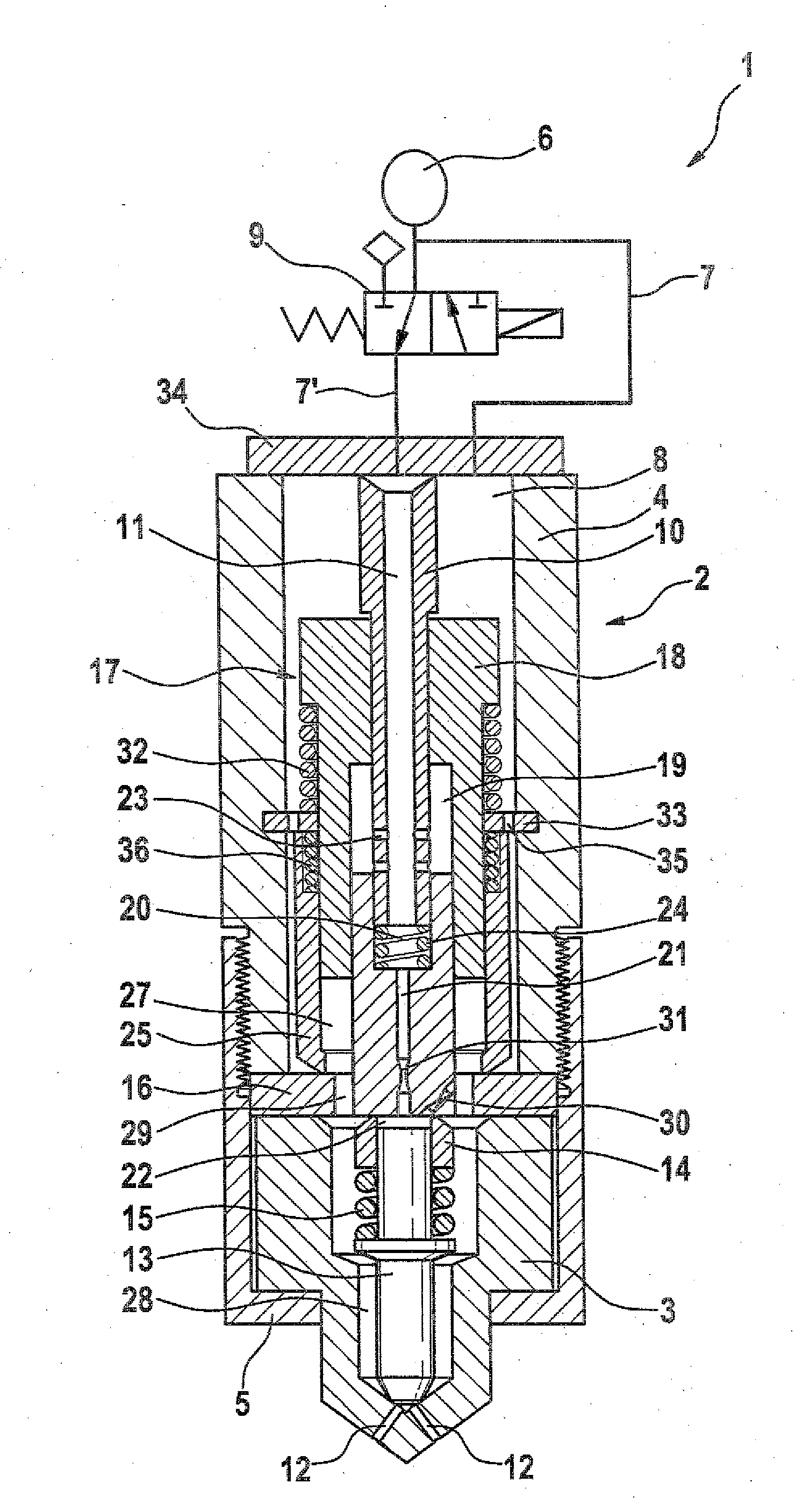
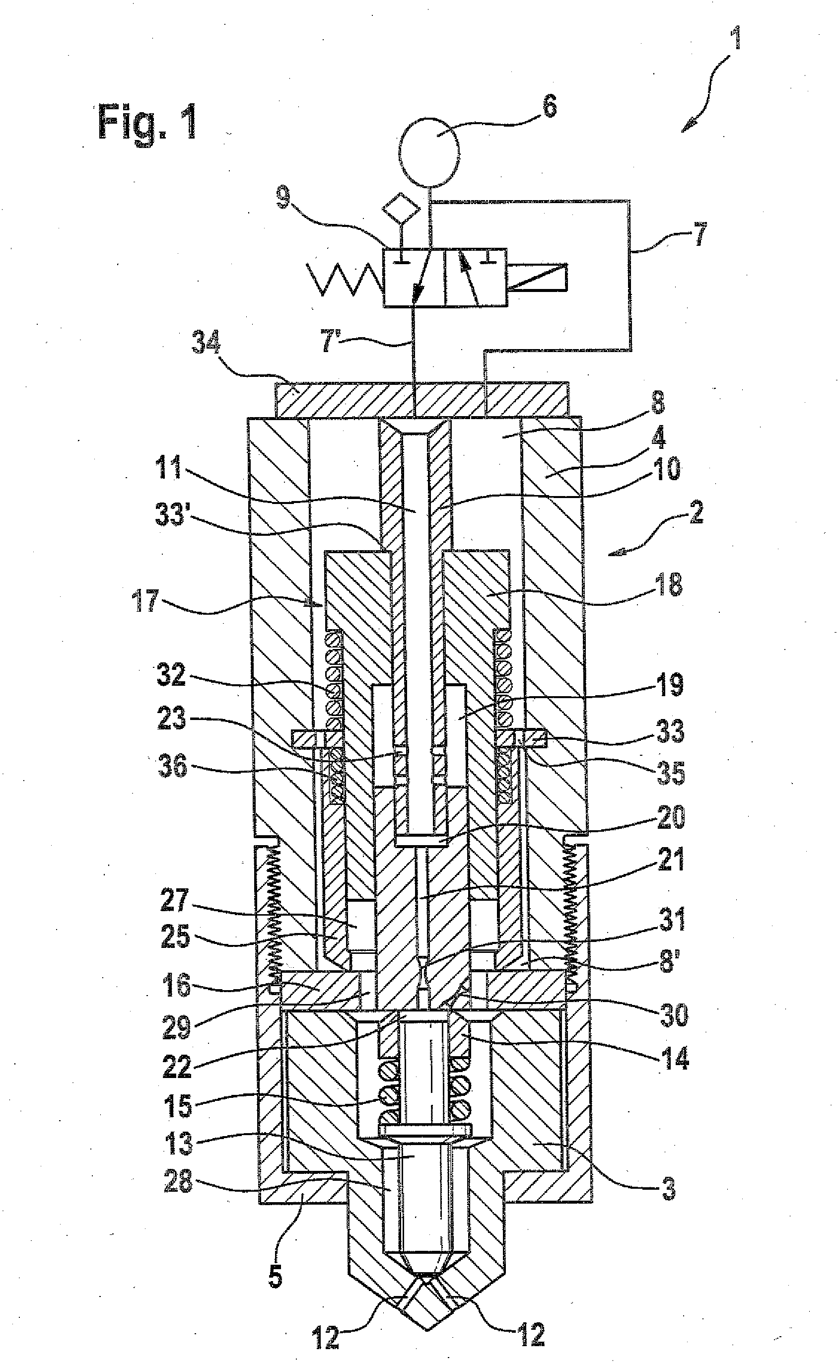
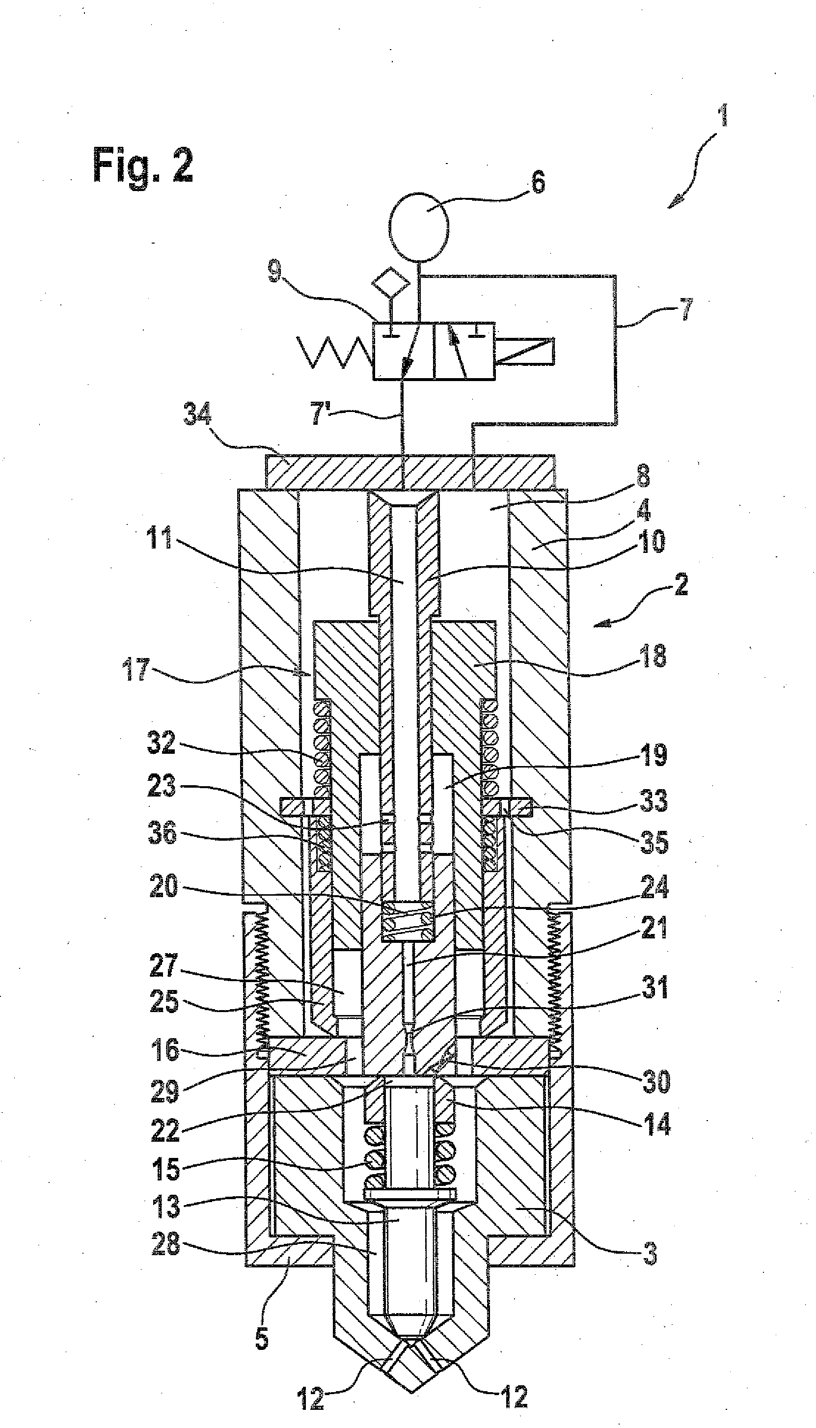
[0014]According to FIGS. 1 through 4, the injector 1 according to the invention includes an injector body 2, which is usually composed of two sections, namely a needle section 3 situated at the bottom and a pressure booster section 4 situated above the former. The two sections 3 and 4 can be attached to each other by a suitable connecting technique, for example a welded connection or a screw connection. In the exemplary embodiments shown, a clamping nut 5 is provided, which encompasses the needle section 3 and clamps it against the pressure booster section 4. The clamping nut 5 is preferably screwed onto the pressure booster section 4.

[0015]The injector 1 is supplied by a high-pressure fuel supply 6, which is connected directly to a high-pressure chamber 8 situated in the injector 1 via a hydraulic line 7 and is connected indirectly to a coupling path 11 situated in a control rod 10 via a hydraulic line 7′ equipped with a valve device 9.

[0016]The needle section 3 is provided with at...


PUM


Abstract

The invention relates to an injector for a fuel injection system of an internal combustion engine, particularly in a motor vehicle, with an injector body which has a pressure booster section and a needle section. At least one injection hole is provided in the needle section. A nozzle needle which has an adjustable stroke is disposed in the needle section for controlling an injection of fuel through the at least one injection hole. A pressure booster is provided for increasing a fuel injection pressure relative to a system pressure. For this purpose, the pressure booster has a double-diameter or stepped piston, a control rod, and a pressure booster bottom which together form the boundary of a coupling chamber. A coupling path extends into the control rod and connects the coupling chamber, over a valve device which is located outside or within the injector, to a high-pressure supply of fuel.

Description

PRIOR ART[0001]The present invention relates to an injector for a fuel injection system of an internal combustion engine, in particular in a motor vehicle.[0002]In order to be able to further reduce pollutant emissions of internal combustion engines, further development has been primarily focused on increasing the injection pressure. In this connection, a large fuel volume in the injector body is advantageously sought in order to be able to keep pressure pulsations in multiple injections to a minimum. A reduction in hydraulic pulsations also has a favorable effect with regard to wear on the nozzle seat. The increase in the injection pressure in known injectors is usually achieved through execution of a pressure boosting, which is used to act on the fuel with a pressure that is greater than the pressure of the system, i.e. is acted on with a multiple of the atmospheric pressure, and at this high pressure, is metered into the combustion chamber. A supply of fuel to the pressure booste...

Claims


Application Information

Patent Timeline
Patent Type & Authority Applications(United States)
IPC IPC(8): F02M43/00B05B1/30
CPCF02M57/025F02M47/027
Inventor MELZER, MARKUSBOLTZ, JOACHIM
Owner ROBERT BOSCH GMBH
Why Eureka
Try Eureka