Optical waveguide, method of its production, and its use

Inactive Publication Date: 2006-06-08
CRYSTAL FIBRE AS
View PDF11 Cites 22 Cited by
  • Summary
  • Abstract
  • Description
  • Claims
  • Application Information

AI Technical Summary

Benefits of technology

[0026] In particular, such a waveguide comprising cross-sectionally extended continuous core elements can contain a larger amount of active material, e.g. dopants such as Er, Yb, or Nd, compa

Problems solved by technology

It is, however, a disadvantage of these fibres of Furusawa that the core is limited in size due to a higher refractive index of the core background material compared to th

Method used


Image

  • Optical waveguide, method of its production, and its use
  • Optical waveguide, method of its production, and its use
  • Optical waveguide, method of its production, and its use

Examples


Example

“Optical Waveguide with 1D Periodic Structure”

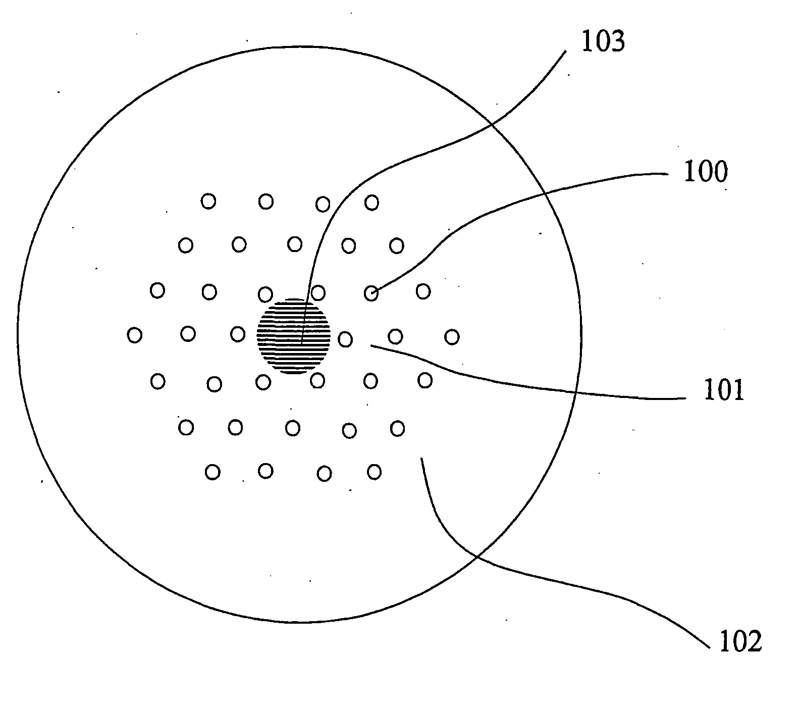
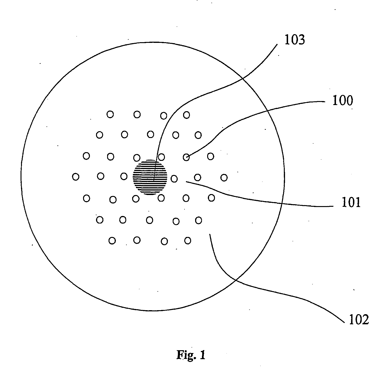
[0145]FIG. 1 shows a cross sectional sketch of an embodiment of an optical waveguide according to the present invention in form of an optical fibre. The fibre comprises elongated cladding elements 100 in the cladding that run along the length of the fibre. The cladding elements are placed in a cladding background material 101 in a periodic structure as further discussed below. The cladding elements surround a core region 103 comprising a structure of core elements as further discussed below. In a cross-section of the fibre, the core region comprises at least one region that exhibits a substantially 1D periodicity of layered core elements. The fibre may comprise a solid outer cladding 102.

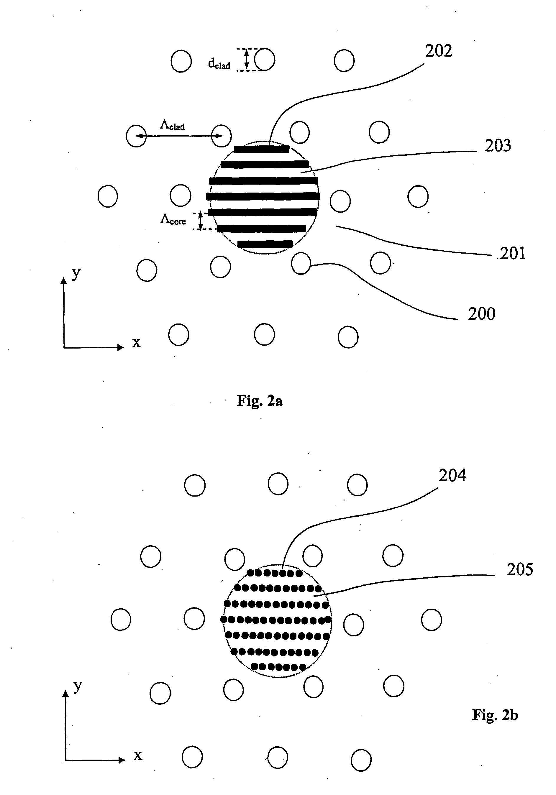
[0146] The fibre has a centre-to-centre separation of the cladding holes Λclad that is significantly larger than a typical period of the substantially 1D periodic core region Λcore. Preferably, Λcore is comparable or smaller than a free-space wavelength...


PUM


Abstract

An optical waveguide with a longitudinal direction and a cross-section perpendicular thereto for propagating optical radiation at a free-space wavelength λ, the optical waveguide comprising: a core region (103), a cladding region (100, 101, 102) surrounding the core region, and a substantially one-dimensional (1D) periodic structure of structural elements with a period A; wherein said structural elements comprises cross-sectionally extended continuous elements; use of such an optical waveguide in optical amplifier, a tunable optical amplifier, an optical laser, and a tuneable optical laser; a preform for its production; and a method of its production.

Description

BACKGROUND OF THE INVENTION [0001] The present invention relates to optical waveguides, in particular optical fibres, said optical waveguides comprising periodic structures of structural elements and exhibiting special polarization properties, and the use of such optical waveguides e.g. for polarization maintaining transmission optical fibres (both for short or long distances), in optical amplifiers, or in lasers, in particular for use in high power laser applications with well-defined polarization state at the output. THE TECHNICAL FIELD [0002] In the field of optical fibres and waveguides, current polarisation maintaining optical fibres and components have a number of disadvantages such as relatively small modes field diameter and / or limited birefringence. Consequently, there is a need for development of improved polarization maintaining (PM) or polarizing components. These include component-type optical fibres for optical fibre amplifiers and lasers, as well as transmission-type ...

Claims


Application Information

Patent Timeline
IPC IPC(8): G02B6/032G02B6/02
CPCG02B6/02338G02B6/02347G02B6/02357G02B6/02361G02B6/02371G02B6/105
Inventor BROENG, JESSKOVGAARD, PETER M. W.KNUDSEN, ERIKJENSEN, JESPER BEVENSEENIELSEN, MARTIN DYBENDAL
Owner CRYSTAL FIBRE AS
Why Eureka
Try Eureka