
Configurable communication board for a gaming machine

a technology of communication board and gaming machine, which is applied in the direction of meter-controlled dispensing apparatus, coin-freed apparatus, instruments, etc., can solve the problems of bringing down a portion of the network, time-consuming and costly construction of these different boards, and susceptibility to damage from devices connected to the boards

Inactive Publication Date: 2006-06-08
IGT
View PDF58 Cites 16 Cited by
  • Summary
  • Abstract
  • Description
  • Claims
  • Application Information

AI Technical Summary

Problems solved by technology

Building these different boards is time consuming and costly.
Another disadvantage of current main communication boards is the susceptibility to damage from devices connected to the board.
When a gaming machine is connected to a network of gaming machines, damage to the main communication board on one machine can bring down a portion of the network.
For example, when a device connected to the main communication board is being replaced or a new device is being installed, the main communication board can be damaged when the main power is not turned off to the gaming machine.
As another example, a player tracking device may generate an electrostatic charge during its operation that can damage the main communication board.
Another disadvantage of current main communication boards is that the whole board is usually replaced when a portion of the board is damaged.
For example, a portion of the main communication board might be damaged that enables communication to a player tracking device while the portion of the board that enables network communications is still operating properly.
Thus, although the portion of the main communication board that provides network communications is still operating properly, communication capabilities along a network segment can be lost while the main communication board is being replaced.

Method used


Image

  • Configurable communication board for a gaming machine
  • Configurable communication board for a gaming machine
  • Configurable communication board for a gaming machine

Examples


Embodiment Construction

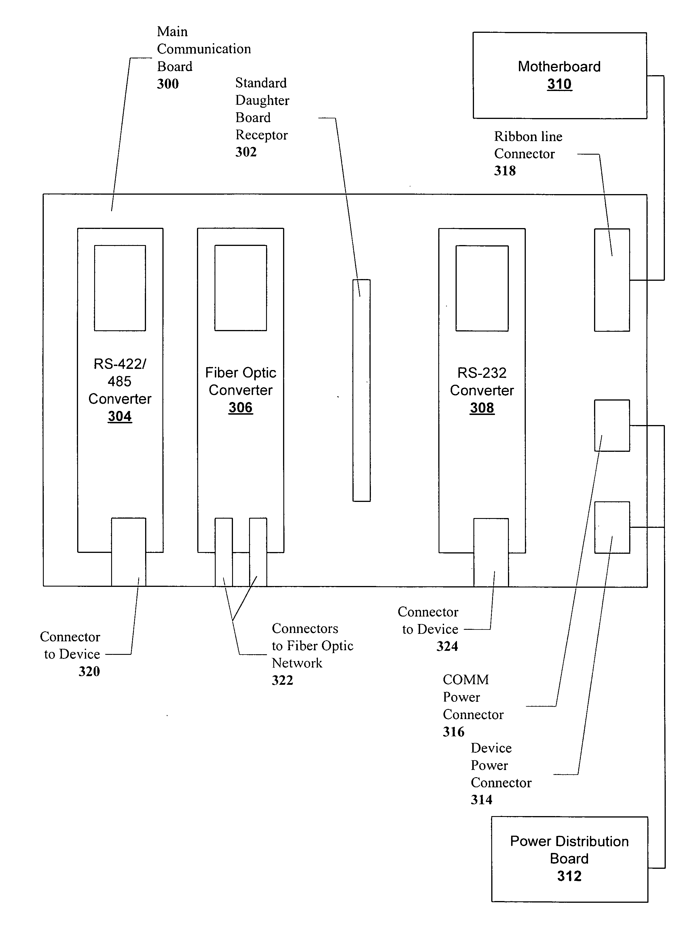
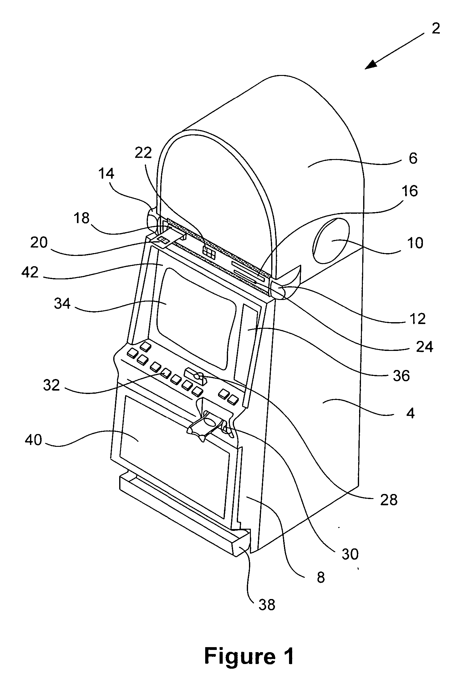
[0024] Turning first to FIG. 1, a video gaming machine 2 of the present invention is shown. Machine 2 includes a main cabinet 4, which generally surrounds the machine interior (not shown) and is viewable by users. The main cabinet includes a main door 8 on the front of the machine, which opens to provide access to the interior of the machine. Typically, the main door 8 and / or any other portals which provide access to the interior of the machine utilize a locking mechanism of some sort as a security feature to limit access to the interior of the gaming machine. Attached to the main door are player-input switches 32, a coin acceptor 28, and a bill validator 30, a coin tray 38, a belly glass 40, and a monitor mask 42. Viewable through the main door is a video display monitor 34 and an information panel 36. The display monitor 34 will typically be a cathode ray tube, high resolution flat-panel LCD, or other conventional electronically controlled video monitor. The information panel 36 i...


PUM


Abstract

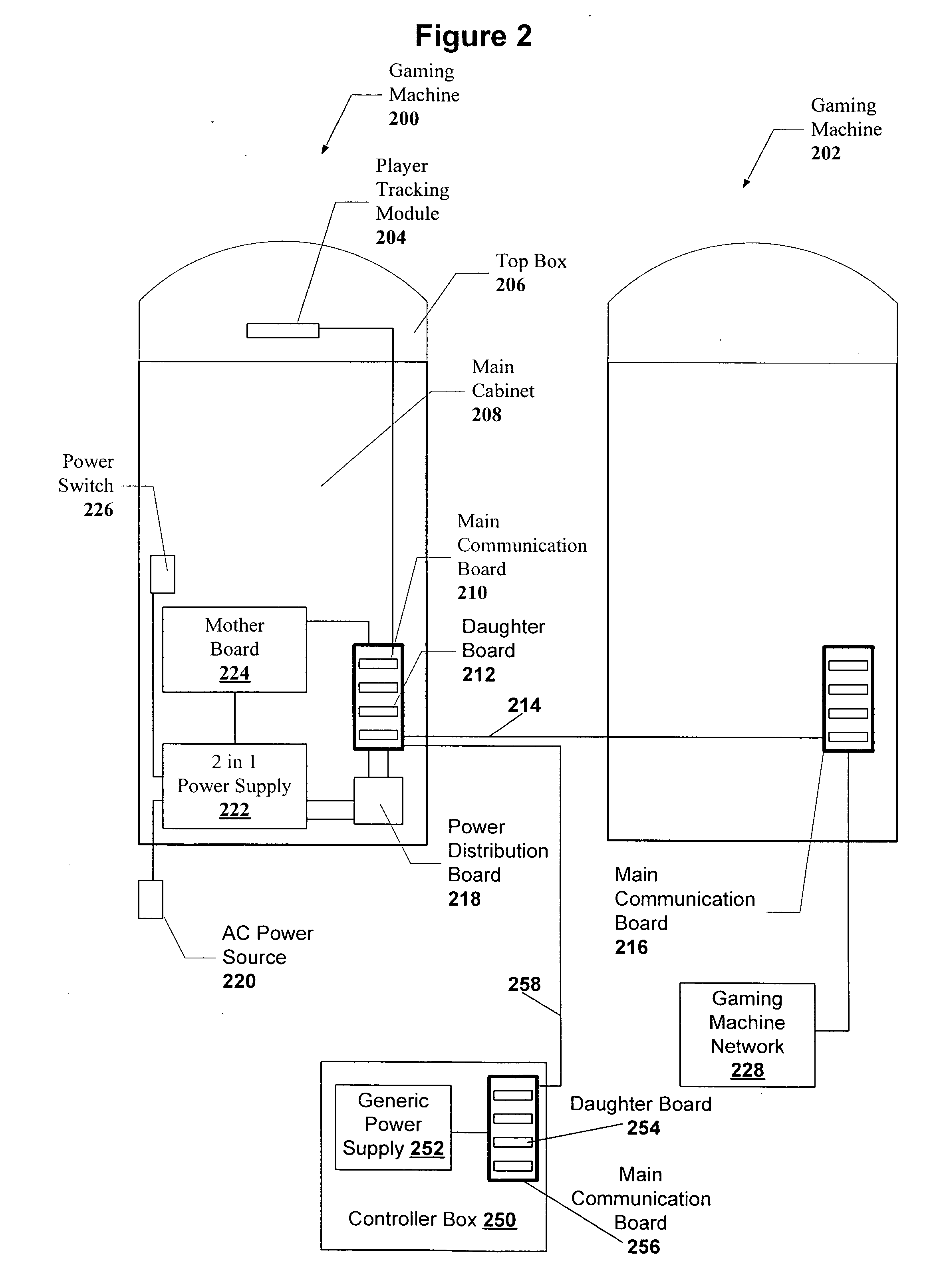
A disclosed communication interface for a gaming machine has a main communication board with one or more standard receptor slots for a plurality of “daughter boards,” each daughter board allowing communication between a master gaming controller and a gaming device or between a master gaming controller and a gaming machine network. The daughter boards may be designed to convert between a number of different communication standards or communication formats. Further, the daughter boards may employ a standard connector that allows the daughter board to be plugged into any of the standard receptor slots on the main communication board. Daughter boards may be removed or installed on the main communication board while the main communication board is receiving power. Further, the main communication board with a plurality of standard receptor slots may accommodate many different types of daughter boards and many different combinations of these types of daughter boards.

Description

CROSS-REFERENCE TO RELATED APPLICATIONS [0001] This is a continuation application of and claims priority under 35 U.S.C. § 120 to commonly owned and co-pending U.S. application Ser. No. 09 / 618,365, entitled “CONFIGURABLE COMMUNICATION BOARD FOR A GAMING MACHINE,” filed on Jul. 18, 2000, which is incorporated herein by reference in its entirety and for all purposes.BACKGROUND OF THE INVENTION [0002] This invention relates to gaming devices for gaming machines such as slot machines and video poker machines. More particularly, the present invention relates to communication converter boards for communication between gaming devices and the gaming machine or for communication between different gaming machines. [0003] There are a wide variety of associated devices that can be connected to a gaming machine such as a slot machine or video poker machine. Some examples of these devices are lights, ticket printers, card readers, speakers, bill validators, coin acceptors, display panels, key pad...

Claims


Application Information

Patent Timeline
Patent Type & Authority Applications(United States)
IPC IPC(8): G06F13/00G07F17/32
CPCG07F17/32G07F17/3202
Inventor NGUYEN, KHANH TRANGSTOCKDALE, JAMES W.
Owner IGT
Learn More