Stackable container with support flanges

a technology of support flanges and containers, applied in the field of containers, can solve the problems of container parts falling, container near or at the bottom of the stack collapse or become misshaped, and achieve the effects of convenient assembly and use, safe stacked during shipping and display, and convenient production

Inactive Publication Date: 2006-06-15
ROYAL BOX GRP LLC
View PDF31 Cites 6 Cited by
  • Summary
  • Abstract
  • Description
  • Claims
  • Application Information

AI Technical Summary

Benefits of technology

[0008] Accordingly, one object of the present invention is to provide a display-ready container with improved anti-nesting capabilities.
[0010] Another object is to provide a display-ready container that is economical to produce.
[0011] A further object of the present invention is to provide a display-ready container that is easy to assemble and use.
[0012] Another object is to provide a display-ready container that can be safely stacked during shipping and display.

Problems solved by technology

A major problem with stacked containers having open tops and sides is that a container may partially fall into or “nest” within the container beneath it.
Another problem is the lack of strength for stacking.
All too often loaded containers near or at the bottom of a stack collapse or become misshaped under the weight of the containers above them.
This impairs the aesthetic appearance of the display sought by the seller, ruins the products within and requires clean up.
If the shelf is already in place, this can interfere with the loading process.
Furthermore, it has been found that in some uses the free end of the shelf can be forced into the container, creating a nesting problem.

Method used


Image

  • Stackable container with support flanges
  • Stackable container with support flanges
  • Stackable container with support flanges

Examples


Embodiment Construction

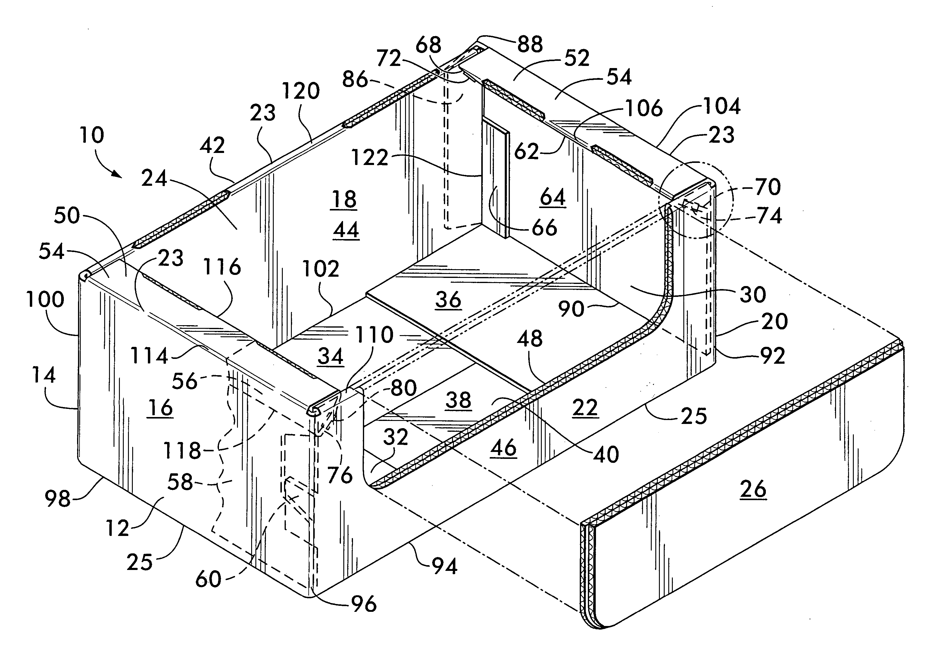
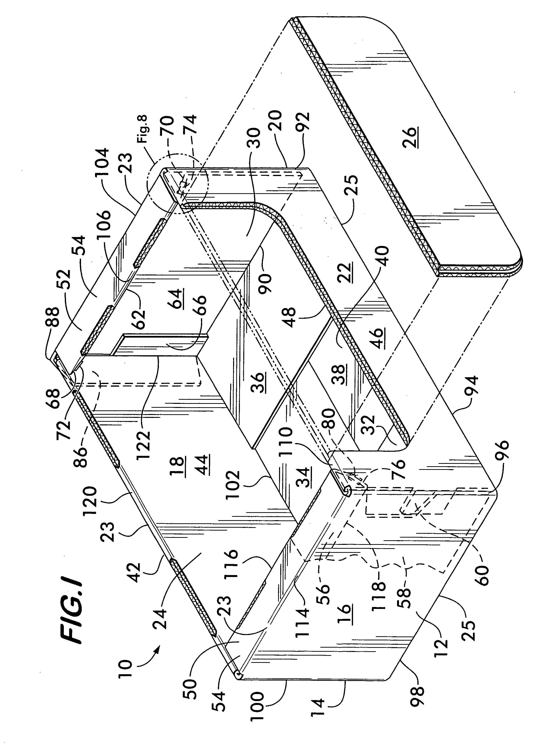
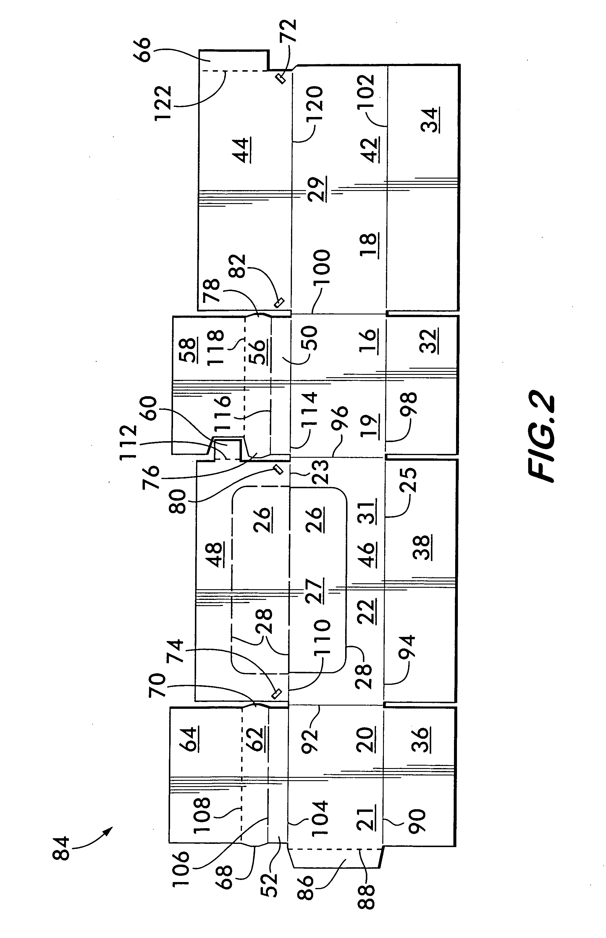
[0025]FIG. 1 shows a container 10 according to the invention. Container 10 is preferably formed of a stiff, lightweight substrate such as corrugated paperboard and comprises a plurality of panels 12 attached to one another along adjacent edges 14 to form a plurality of sidewalls 16, 18, 20 and 22. The sidewalls surround a central space 24 where merchandise is received for storage, transport and display. The sidewalls have an upper edge 23 and a lower edge 25. Container 10 is depicted without a top as it might be seen in a display at a market. Sidewall 22 preferably has a removable panel portion 26 defined by a plurality of interconnected perforations 28 (see FIG. 2), the panel portion 26 being shown removed to provide an opening 30 in the container 10 allowing display and access to the goods therein even when another container is stacked atop container 10.

[0026] Flaps 32, 34, 36 and 38 extend respectively from each sidewall 16, 18, 20 and 22 and are folded inwardly toward the centr...


PUM


Abstract

A container is disclosed having a plurality of interconnected panels forming sidewalls surrounding a central space. Flaps extend from lower sidewall edges and fold along fold lines to form a bottom. Support flanges are arranged along upper sidewall edges on oppositely facing sidewalls. The support flanges are oriented at right angles to the sidewalls and provide a support surface allowing the containers to be stacked one atop another without collapsing or nesting within each other. Each support flange is supported by a truss formed by a panel segment extending angularly from the support flange to a support panel biased against the sidewall to which the support flange is attached by a retaining flap extending from an inner sidewall layer. Locking tabs at the ends of each panel segment are received within recesses positioned in sidewall panels perpendicular to the support flanges. The container is transformed from a knockdown formed from a unitary blank.

Description

RELATED APPLICATION [0001] This application is based on and claims the benefit of U.S. Provisional Application No. 60 / 354,419, filed Feb. 5, 2002, and U.S. Provisional Application No. 60 / 359,125 filed Feb. 22, 2002.FIELD OF THE INVENTION [0002] The invention relates to containers used for packaging, shipping and displaying goods. More particularly, the invention relates to display containers such as corrugated paperboard boxes having flanges to facilitate the stacking of such containers on top of one another. BACKGROUND OF THE INVENTION [0003] Display containers, for example, boxes of corrugated paperboard, are widely used for shipping and marketing products. Such containers are especially containers of candy are shipped to the store in stacked form. Store personnel remove the tops of the containers and, in many cases, fold down or remove a side display panel from the container which exposes the candy within the container to view and allows access thereto by the consumer. The contai...

Claims


Application Information

Patent Timeline
Patent Type & Authority Applications(United States)
IPC IPC(8): B65D25/54B65D5/00B65D5/02B65D5/16B65D5/66B65D21/02B65D21/032
CPCB65D5/001B65D5/0236B65D5/0281B65D5/16B65D5/3621B65D5/6605
Inventor KANTER, ALLENJAFFE, PETER S.TIBBELS, BRIAN J.
Owner ROYAL BOX GRP LLC
Why Eureka
Try Eureka