Bandpass filter

a filter and bandpass technology, applied in the field of bandpass filters, can solve the problems of increasing signal loss and the majority of harmonic suppression not being as good as desired

Inactive Publication Date: 2006-06-15
RAYTHEON CO
View PDF17 Cites 19 Cited by
  • Summary
  • Abstract
  • Description
  • Claims
  • Application Information

AI Technical Summary

Problems solved by technology

Electrically, using lowpass filters increase signal loss, and the suppression of the harmonics for the most part is not as good as desired.

Method used


Image

  • Bandpass filter
  • Bandpass filter
  • Bandpass filter

Examples


Embodiment Construction

[0011] In the following detailed description and in the several figures of the drawing, like elements are identified with like reference numerals.

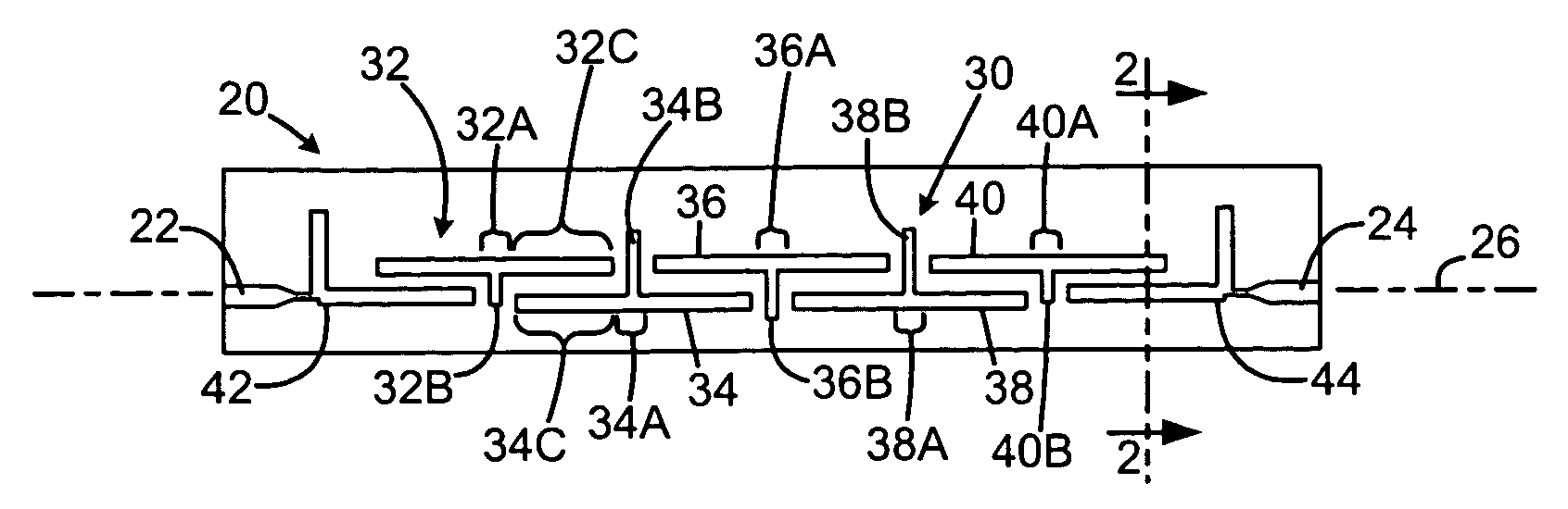
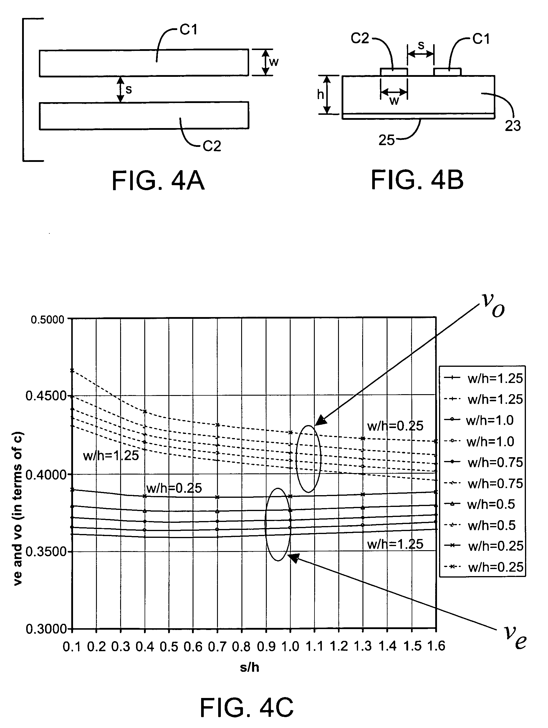
[0012] In an edge coupled filter fabricated in a planar transmission line medium, such as microstrip or stripline, energy is propagated through the filter through edge-coupled resonator elements or conductor strips. Harmonics in the filter response appear due to the mismatch in phase velocities of the even and odd modes. In microstrip coupled lines, the odd mode travels faster than the even mode. Also, the odd mode tends to travel along the outer edges of the microstrip coupled lines or conductor strips, while the even mode tends to travel near the center. In an exemplary embodiment, to suppress the harmonics of the filter, a means for equalizing the even and odd mode electrical lengths is provided.

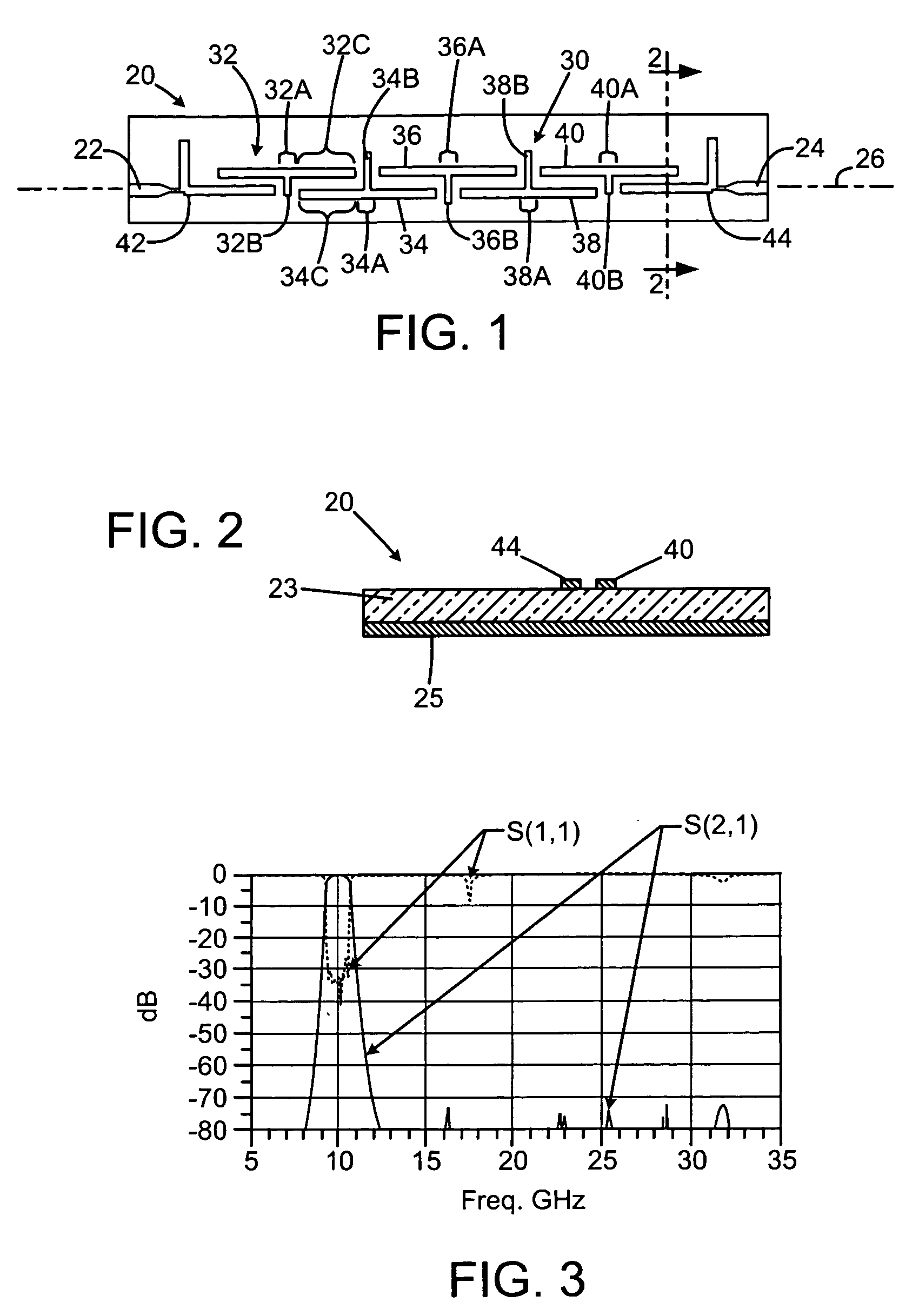
[0013] In an exemplary embodiment illustrated in FIG. 1 and, a microstrip filter 20 comprises spatially separated input / output (I / O) ports 22...


PUM


Abstract

An edge-coupled filter includes a phase velocity compensation transmission line section comprising a series of spaced alternating T-shaped conductor portions.

Description

BACKGROUND [0001] Most microwave filters built using microstrip transmission lines have a tendency of not suppressing 2nd ,3rd and 4th harmonic signals. Traditionally, the way to solve this problem is to add a lowpass filter at the two ends of a bandpass filter. Physically, this makes the filter structure bigger. Electrically, using lowpass filters increase signal loss, and the suppression of the harmonics for the most part is not as good as desired. SUMMARY OF THE DISCLOSURE [0002] An edge-coupled filter includes a phase velocity compensation transmission line section comprising a series of alternating T-shaped conductor portions.BRIEF DESCRIPTION OF THE DRAWINGS [0003] Features and advantages of the disclosure will readily be appreciated by persons skilled in the art from the following detailed description when read in conjunction with the drawing wherein: [0004]FIG. 1 is a layout of an exemplary embodiment of a bandpass filter. [0005]FIG. 2 is a cross-sectional diagrammatic view ...

Claims


Application Information

Patent Timeline
Patent Type & Authority Applications(United States)
IPC IPC(8): H01P1/203
CPCH01P1/20336H01P1/20372H01P1/20381H01P1/203
Inventor AKALE, TAMRATWANG, ALLEN
Owner RAYTHEON CO
Why Eureka
Try Eureka