Broadcast signal receiver

a receiver and broadcast signal technology, applied in the field of broadcast signal receivers, can solve problems such as damage to the tuner circui

Inactive Publication Date: 2006-06-15
FUNAI ELECTRIC CO LTD
View PDF1 Cites 5 Cited by
  • Summary
  • Abstract
  • Description
  • Claims
  • Application Information

AI Technical Summary

Benefits of technology

[0009] The present invention is made to solve the above-mentioned conventional problems, and purposes to provide a broadcast signal receiver which can protect a tuner circuit and a power source circuit of a broadcast signal receiver from an over current even when a drive voltage used for switching an effective signal receiving direction of a multi-directional antenna is applied to an outside conductor of a coaxial cable connected to the broadcast signal receiver due to faulty wiring.
[0016] an over current interruption switch provided between the coaxial connector and the tuner circuit for interrupting an over current flowing toward the tuner circuit, thereby when a second coaxial cable used for connecting between the antenna controller and the multi-directional antenna is erroneously connected to the coaxial connector and a drive voltage used for switching the effective signal receiving direction of the multi-directional antenna is applied to the coaxial connector, the over current due to the drive voltage is interrupted by the over current interruption switch so that the tuner circuit is protected from the over current.
[0017] By such a configuration, even when the drive voltage used for switching the effective signal receiving direction of the multi-directional antenna is applied to the coaxial connector from the antenna controller caused by faulty wiring of the first coaxial cable, the over current interruption switch interrupts the over current due to the drive voltage and flowing toward the tuner circuit, so that the tuner circuit is protected from the over current. Consequently, it is possible to prevent the break out of the broadcast signal receiver due to faulty wiring.
[0019] Since polymeric protection switch can easily be returned to the conduction state, the operator can easily re-connects the antenna controller and the broadcast signal receiver without any troublesome operation.
[0021] Still furthermore, it is preferable that the control circuit detects the drive voltage applied to the coaxial connector and shuts off output of the power supply circuit. Thereby, safety of the broadcast signal receiver can be increased.

Problems solved by technology

If such a faulty wiring is passed undetected, the driving voltage used for switching the effective signal receiving direction of the multi-directional antenna 2 is applied to a tuner circuit of the broadcast signal receiver 1, so that the tuner circuit may be damaged.

Method used


Image

  • Broadcast signal receiver
  • Broadcast signal receiver
  • Broadcast signal receiver

Examples


Embodiment Construction

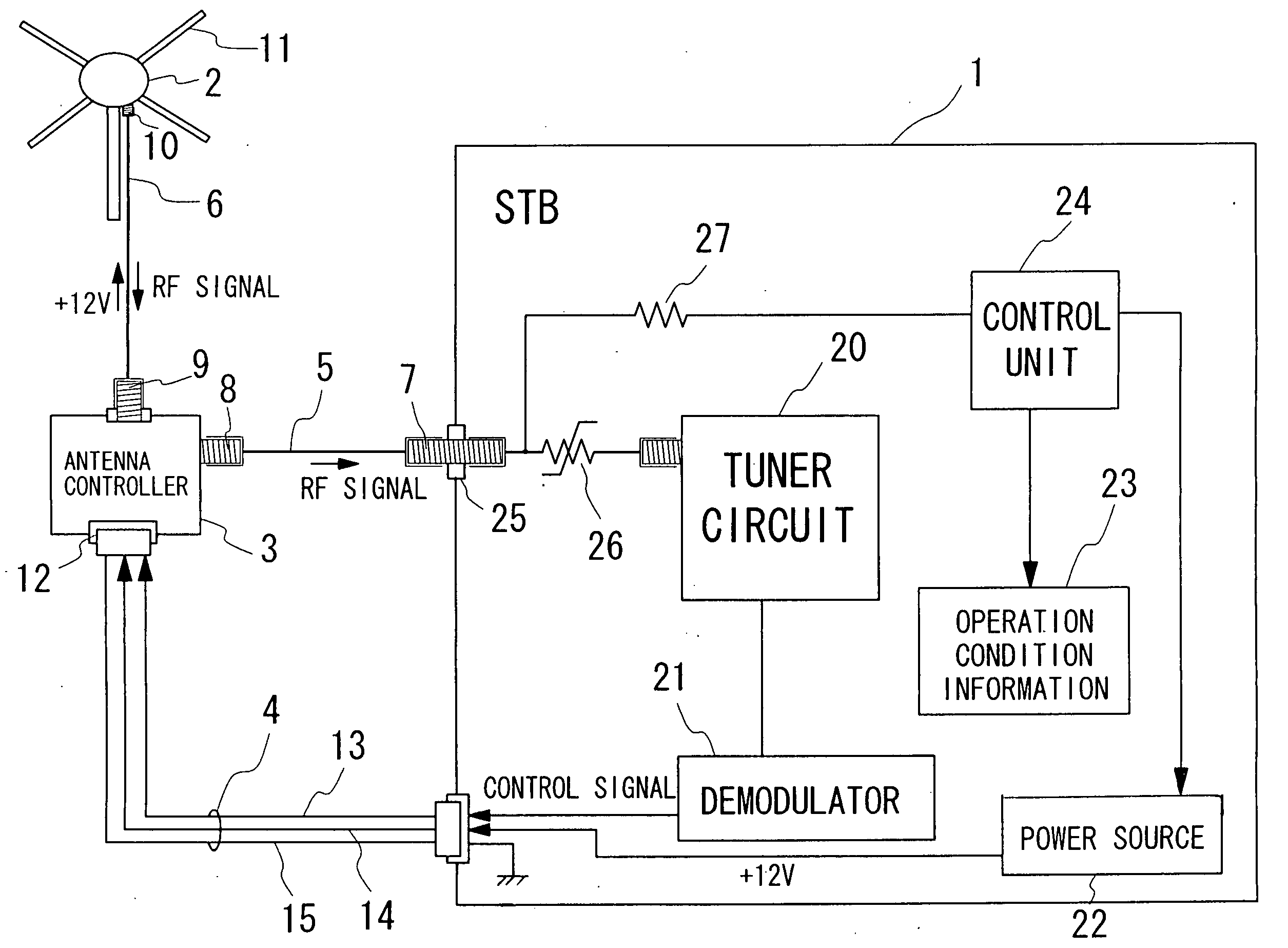
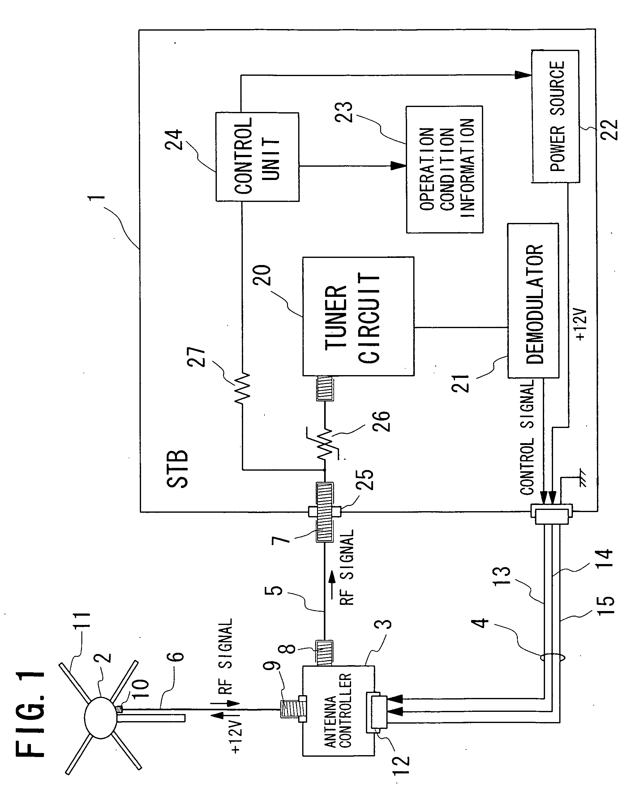
[0026] A broadcast signal receiver (STB) in accordance with an embodiment of the present invention is described with reference to the figures. FIG. 1 shows a configuration of a broadcast signal receiver 1 and a state that a multi-directional antenna and an antenna controller are normally connected to the broadcast signal receiver 1.

[0027] A multi-directional antenna 2 having plural signal receiving directions is connected to the broadcast signal receiver 1 through an antenna controller (antenna control means) 3. The broadcast signal receiver 1 and the antenna controller 3 are connected by a modular cable 4 and a first coaxial cable 5. The multi-directional antenna 2 and the antenna controller 3 are connected by a second coaxial cable 6.

[0028] The first coaxial cable 5 is connected between a first coaxial connector 7 provided on the broadcast signal receiver 1 and a second coaxial connector 8 provided on the antenna controller 3. On the other hand, the second coaxial cable 6 is con...


PUM


Abstract

In a broadcast signal receiver to which a multi-directional antenna having a plurality of signal receiving directions is connected through an antenna controller for controlling the multi-directional antenna, even when the antenna controller is erroneously connected to the broadcast signal receiver, a tuner circuit and a power supply circuit of the broadcast signal receiver is protected from over current caused by a driving voltage of the antenna controller used for switching the effective signal receiving direction of the multi-directional antenna. A polymeric protection switch is provided between a connector to which a coaxial cable connected to the antenna controller be connected and the tuner circuit.

Description

BACKGROUND OF THE INVENTION [0001] 1. Field of the Invention [0002] The present invention relates to a broadcast signal receiver corresponding to multi-directional antenna. [0003] 2. Description of the Related Art [0004] In recent years, a broadcast signal receiver called “set top box” (it is designated by a reference of STB in figures) corresponding to multi-directional antenna is put in practical use and familiarized. The multi-directional antenna is connected to the broadcast signal receiver through an antenna controller, so that an effective signal receiving direction thereof is controlled. [0005]FIG. 3 shows a connection among the multi-directional antenna, the antenna controller and the broadcast signal receiver. The antenna controller 3 and the broadcast signal receiver 1 are connected with a modular cable 4 and a coaxial cable 5 each other. The modular cable 4 has a control signal transmission line 13 used to transmit a control signal for controlling the multi-directional an...

Claims


Application Information

Patent Timeline
Patent Type & Authority Applications(United States)
IPC IPC(8): H01Q1/50H04B1/18H04N5/44
CPCH01Q1/50
Inventor FUJIMOTO, MASATO
Owner FUNAI ELECTRIC CO LTD
Why Eureka
Try Eureka