Non-synchronous boost converter including low-voltage device for load disconnection

a boost converter and low-voltage device technology, applied in the field of voltage converters, can solve the problems of poor converter circuit efficiency, high-voltage device not only cost, but also has a greater on-resistan

Active Publication Date: 2010-02-04
RICHTEK TECH
View PDF4 Cites 4 Cited by
  • Summary
  • Abstract
  • Description
  • Claims
  • Application Information

AI Technical Summary

Benefits of technology

[0009]Preferably, a current supply circuit is connected to the output voltage terminal to provide stable pre-charge current and short circuit protection current to the capacitor.

Problems solved by technology

Unfortunately, a high-voltage device not only is costly but also has a greater on-resistance, thereby causing poor efficiency in the converter circuit.

Method used


Image

  • Non-synchronous boost converter including low-voltage device for load disconnection
  • Non-synchronous boost converter including low-voltage device for load disconnection
  • Non-synchronous boost converter including low-voltage device for load disconnection

Examples


Embodiment Construction

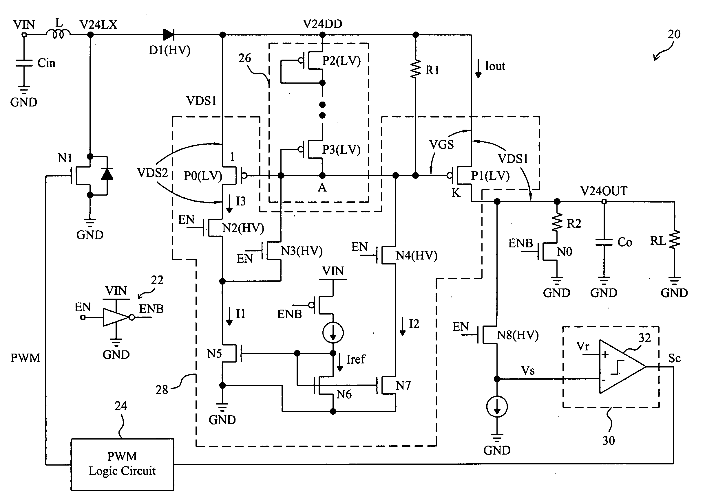
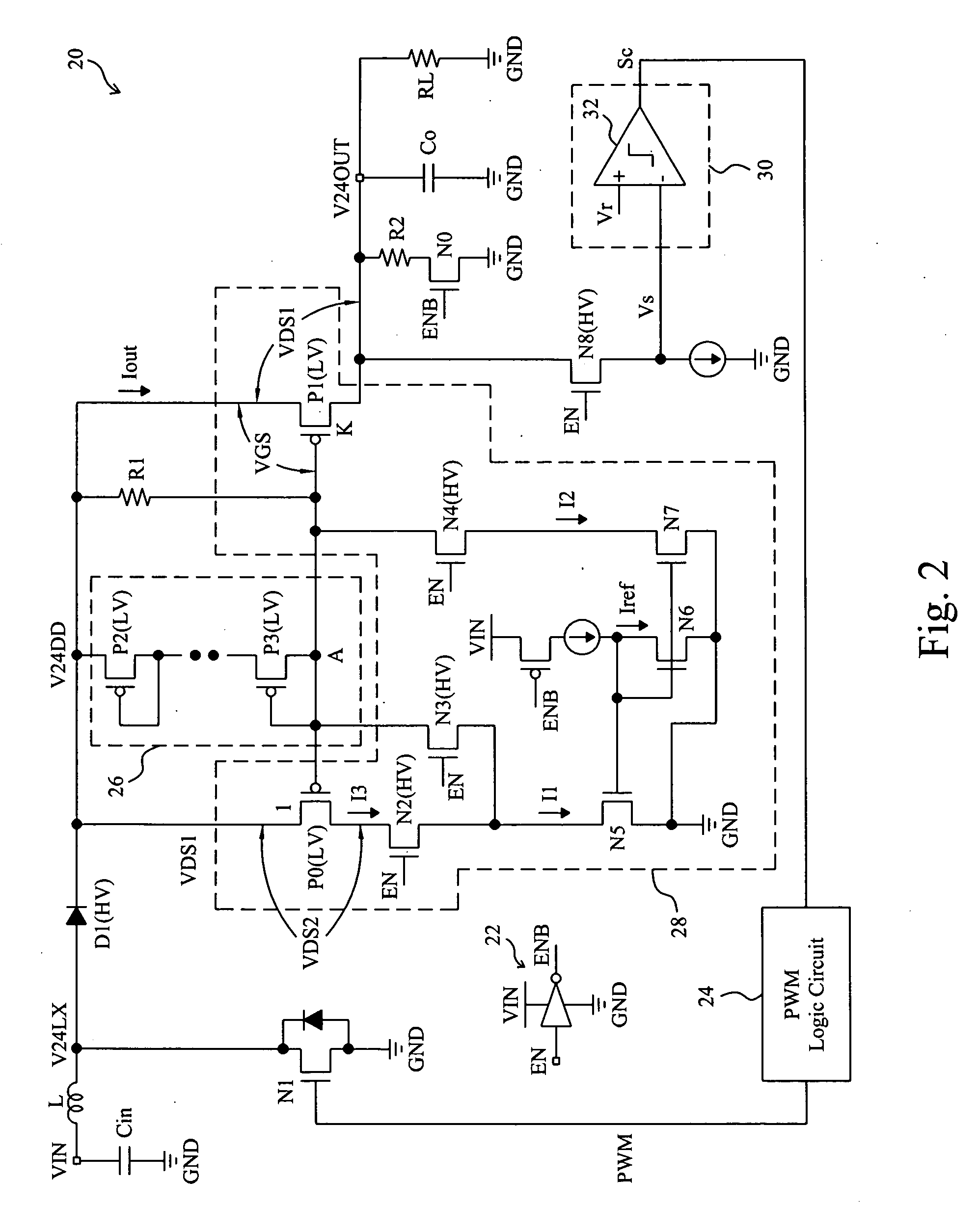
[0018]FIG. 2 shows an embodiment according to the present invention. In a non-synchronous boost converter 20, an input voltage terminal VIN is used to connect to a power source to receive an input voltage, an inductor L is connected between the input voltage terminal VIN and a switched node V24LX, a power switch N1 is connected between the switched node V24LX and a ground terminal GND, an output voltage terminal V24OUT is used to provide an output voltage, an embedded diode D1 is connected between the switched node V24LX and the output voltage terminal V24OUT, a capacitor Co is connected to the output voltage terminal V24OUT, and a transistor P1 is connected between the diode D1 and the output voltage terminal V24OUT. In response to a control signal PWM provided by a PWM logic circuit 24, the power switch N1 is switched to generate an output current lout flowing through the inductor L, the embedded diode D1 and the transistor P1 to charge the capacitor Co to generate the output volt...


PUM


Abstract

A non-synchronous boost converter includes a low-voltage device connected between the input voltage terminal and the output voltage terminal of the converter. When the converter is shutdown, the low-voltage device disconnects the output voltage terminal and the input voltage terminal. Since it is a low-voltage device used in the converter for load disconnection, the efficiency of the converter is improved with lower cost.

Description

FIELD OF THE INVENTION[0001]The present invention is related generally to voltage converters and, more particularly, to a non-synchronous boost converter using a low-voltage device for load disconnection.BACKGROUND OF THE INVENTION[0002]As shown in FIG. 1, a conventional non-synchronous boost converter 10 generates output current by switching a power switch (not shown) in a controller chip 12, which flows through an inductor L1 and a Schottky diode D1 to charge a capacitor C2 to generate an output voltage VOUT. Since the forward voltage VF of the Schottky diode D1 is small, this converter circuit will have good efficiency in power conversion. However, when the boost converter 10 is shutdown by a signal Enable but the input voltage VIN provided by batteries is still high, for example at 3.7V, the Schottky diode D1 will be still conductive and thereby produce a non-zero output voltage, for example 3.3V, at the output voltage terminal VOUT. Therefore, leakage current will be present in...

Claims


Application Information

Patent Timeline
Patent Type & Authority Applications(United States)
IPC IPC(8): G05F1/00
CPCH02M3/158
Inventor HUANG, TSUNG-WEILIN, SHUN-MUCHEN, JIEN-SHENGCHU, KWAN-JEN
Owner RICHTEK TECH
Why Eureka
Try Eureka