Parasitic battery drain test assembly for multiple component vehicle circuitry analysis

a technology of multiple component vehicle and test assembly, which is applied in the direction of insulated conductors, cables, instruments, etc., can solve the problems of circuit breakage and excessive battery drain, and achieve the effect of safe detection of curren

Active Publication Date: 2016-08-11
LISLE CORPORATION
View PDF2 Cites 5 Cited by
  • Summary
  • Abstract
  • Description
  • Claims
  • Application Information

AI Technical Summary

Benefits of technology

[0010]The bypass switch, when open, provides a series circuit between a multimeter (current measuring device) and the vehicle disconnected battery cable and open pole contact. When the bypass switch is closed, a parallel circuit to the current measuring device (multimeter) is maintained. The fuse of the first assembly component is set or rated at a lower level than the fuse of the second assembly component to provide protection to the multimeter or current measuring device.
[0012]Because the current sensing device is to be set on a scale which measures low amperage, the fuses in the circuitry protect the sensing or current measurement meter when the switch is either in the “on” or “off” position. That is, when the vehicle engine is initially turned off, the bypass switch will be “on” or in the closed position and thus the higher rated fuse will sense battery load or drain. If the drain or load is in excess of the fuse rating, the circuit will be broken and will protect the multimeter which has not yet been placed in a circuit to the battery. If the fuse of the second assembly does not “blow”, then the multimeter will sense current when the bypass switch is opened or turned to the “off” position. That is, the circuit to and including the multimeter will be closed. Thus, initial current or power consumption readings will be representative of the initial powering down of vehicle components as the current sensing and measurement device is completed. As the automotive modules enter a sleep mode, the power consumption or current readings should decline assuming there is minimal parasitic drain of power. The bypass switch can then remain in the “off” position and all parasitic load current will safely flow through the multimeter or ammeter for continued analysis. Also, since the first assembly component is fused, the current sensing device will be protected from a sudden current drain spike or event.
[0015]Typically, the second assembly of paired cables, connected to one of the battery posts and a disconnected battery cable, are fused for higher amperage than the fused cable associated with the first assembly of paired cables that are connected to the multimeter or current measurement device. For example, the fuse in a cable connected to the battery post may be a ten (10) amp fuse or less and a fuse in one of the cables to the multimeter will be a seven and one half (7.5) amp fuse or less. With the on / off or bypass switch “on” (i.e., the switch closed), the parasitic drain tester provides a direct current path between the cables attached to a vacant battery post and a disconnected battery cable disconnected from that post. If the current flow through the cables connecting the battery post and a disconnected battery cable exceeds ten amps, then the fuse blows and the bypass switch is protected from possible damage.
[0017]Thus, it is an object and aspect of the invention to provide a quick method to check current draw from a car battery when the vehicle associated with the battery is turned “off”.
[0018]A further object and aspect of the invention is to provide a means to utilize a typical multimeter or ammeter to provide for measurement of parasitic drain without exposing the multimeter to excessive current and without an expensive circuit breaker incorporated into the multimeter as part of the design thereof. Thus, a safety factor is included in the design of the disclosed assembly to protect the multimeter while at the same time enabling collection of data relating to parasitic drain.
[0020]Another object of the invention is to provide a tool of component parts which may comprise a kit including a wiring harness assembly and a current sensing and measurement device which measure parasitic drain readings over time without excessive supervision by a mechanic or technician thereby enabling the mechanic or technician to perform service on the vehicle while securing the parasitic drain readings.

Problems solved by technology

If the current exceeds the fuse rating of the second assembly component, the circuit will be broken indicating excessive battery drain.

Method used


Image

  • Parasitic battery drain test assembly for multiple component vehicle circuitry analysis
  • Parasitic battery drain test assembly for multiple component vehicle circuitry analysis
  • Parasitic battery drain test assembly for multiple component vehicle circuitry analysis

Examples


Embodiment Construction

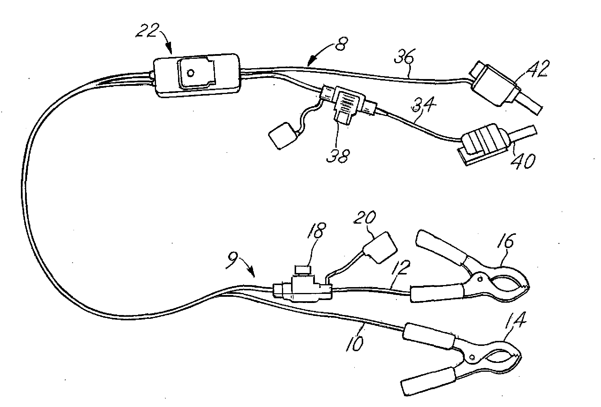
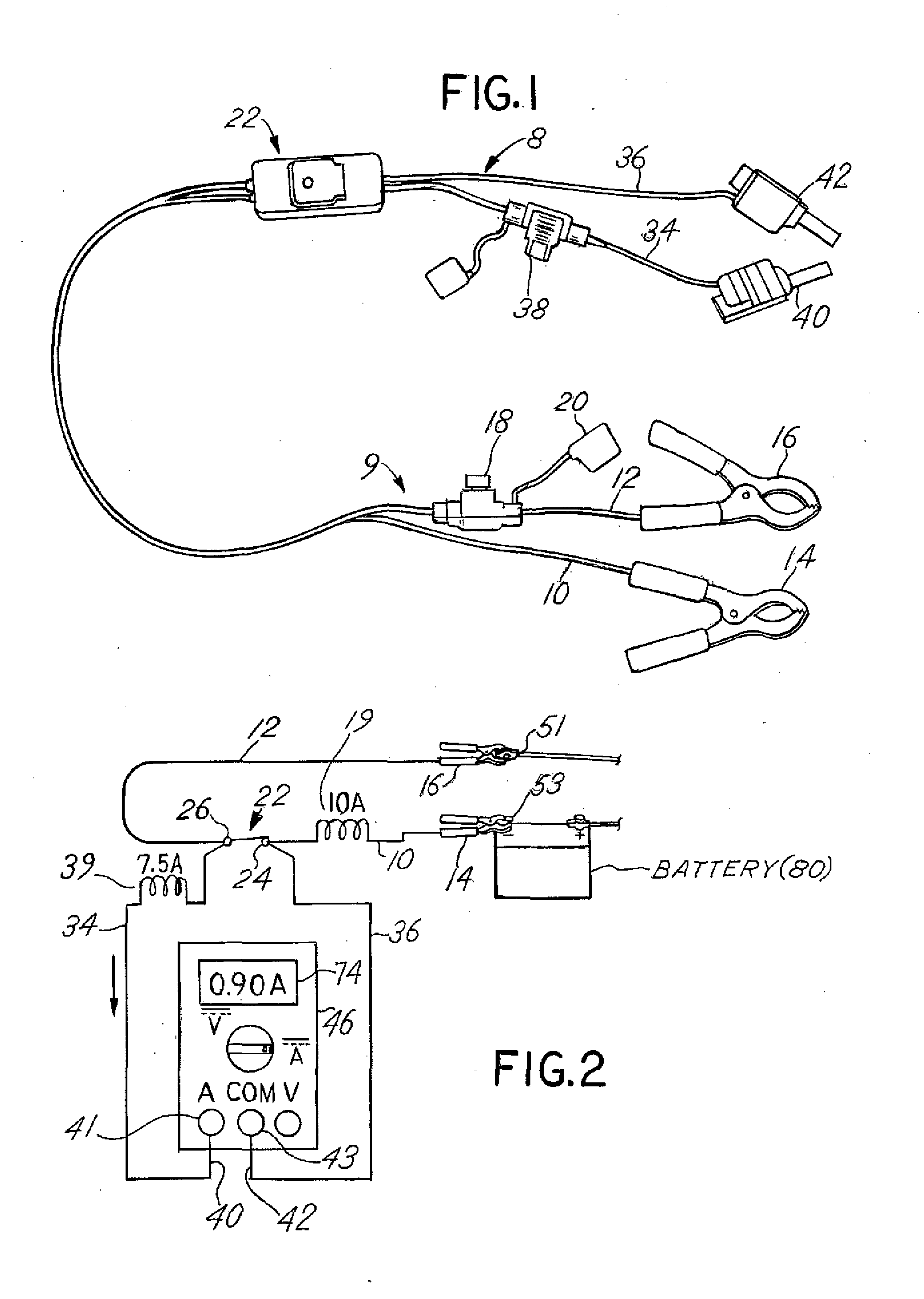
[0027]FIG. 1 depicts a wiring harness assembly which may be manufactured and sold separately from a current measurement device such as a multimeter or an ammeter. Thus, the harness assembly of FIG. 1 includes the benefit of a low cost assembly that may be used with a standard diagnostic tool available to and maintained by many technicians and mechanics. The combination of such elements results in the utilization of a very straightforward, simple and useful harness construction or assembly with a current measurement device that has multiple uses. Because of the design for the harness assembly, the current measurement device is subject to protection when utilized to determine parasitic drain. The harness depicted in FIG. 1 may thus be combined with a current sensing and measurement device to provide a kit for measurement of parasitic current drain.

[0028]Referring to FIG. 1 and FIG. 2, the harness assembly includes a first assembly component 8 comprising a first pair of conductive cabl...


PUM

PropertyMeasurementUnit
current measurementaaaaaaaaaa
direct current measurementaaaaaaaaaa
voltageaaaaaaaaaa

Abstract

A cable harness assembly useful in combination with a current measurement device includes first and second pairs of cables each pair having a lead connected to a separate pole of a bypass switch, each pair including one of said cables fused, said first pair of cables having leads connectable to a current measurement device and the second pair of cables connectable to direct current electric power course which is incorporated with circuitry involving various control and other modules potentially susceptible to parasitic current drain. The first and second pair of cables each includes one cable fused, the fuse rating of a second pair rated higher than said first pair rating, the first pair having leads configured connect to a current measurement device and the second pair having leads connectable respectively to the direct current power source and a circuit powered by the power source.

Description

CROSS REFERENCE TO RELATED APPLICATION[0001]This is a utility application claiming priority to provisional application, Ser. No. 62 / 114,292 filed Feb. 10, 2015.BACKGROUND OF THE INVENTION[0002]In a principal aspect the present invention comprises a parasitic battery drain test assembly incorporating a current measuring device such as a multimeter or amp meter and a wiring harness which enables determination of the parasitic current drain associated with an electrical system of a mechanized device such as a motor vehicle.[0003]Modern motor vehicles include complex electronic circuitry and computer control modules designed to provide power to sensors, the vehicle ignition system, and multiple other electrically powered components including various monitoring systems, safety systems and the like. The power to operate these systems is typically sourced from the vehicle battery that is charged, as needed, by operation of the vehicle engine. However, when the vehicle engine is not continu...

Claims


Application Information

Patent Timeline
Patent Type & Authority Applications(United States)
IPC IPC(8): G01R31/00G01R31/36H01B7/00G01R15/12G01R31/58
CPCG01R31/006H01B7/0045G01R31/3696G01R15/12G01R31/007G01R31/364G01R31/52G01R31/58
Inventor FASNACHT, CHRISTOPHER L.SUNDERMAN, PHILIP E.
Owner LISLE CORPORATION
Why Eureka
Try Eureka