Method and system for shoot-through protection

a technology of circuit components and shoot-through current, applied in the direction of pulse technique, process and machine control, instruments, etc., can solve the problems of premature shutdown, inability to reliably detect the shoot-through current, and inability to interlock and anti-saturation designs, so as to reduce the risk of premature shutdown, accurately detect the shoot-through current, and reduce the rate of increase in the shoot-through current.

Active Publication Date: 2014-06-10
MKS INSTR INC
View PDF14 Cites 4 Cited by
  • Summary
  • Abstract
  • Description
  • Claims
  • Application Information

AI Technical Summary

Benefits of technology

[0006]The invention features methods and circuits for protecting circuit components against shoot-through current. Any of the particular embodiments described below can realize one or more of the following advantages. Switching devices can be reliably shutdown even in the presence of noise. The risk of premature shutdowns of the switching devices can also be minimized. Active sensing can provide a more accurate approach to controlling switching than using current measured from the gate / base terminal of a transistor. In addition, the rate of increase in a shoot-through current can be delayed to provide sufficient time for appropriate feedback is processed to accurately detect the shoot-through current and enact appropriate protection measures in response to the detection.

Problems solved by technology

However, interlock and anti-saturation designs are generally not reliable because they either do not account for noise factors in the environment or are too sensitive to changes in the environment resulting in premature shutdowns.

Method used


Image

  • Method and system for shoot-through protection
  • Method and system for shoot-through protection
  • Method and system for shoot-through protection

Examples


Embodiment Construction

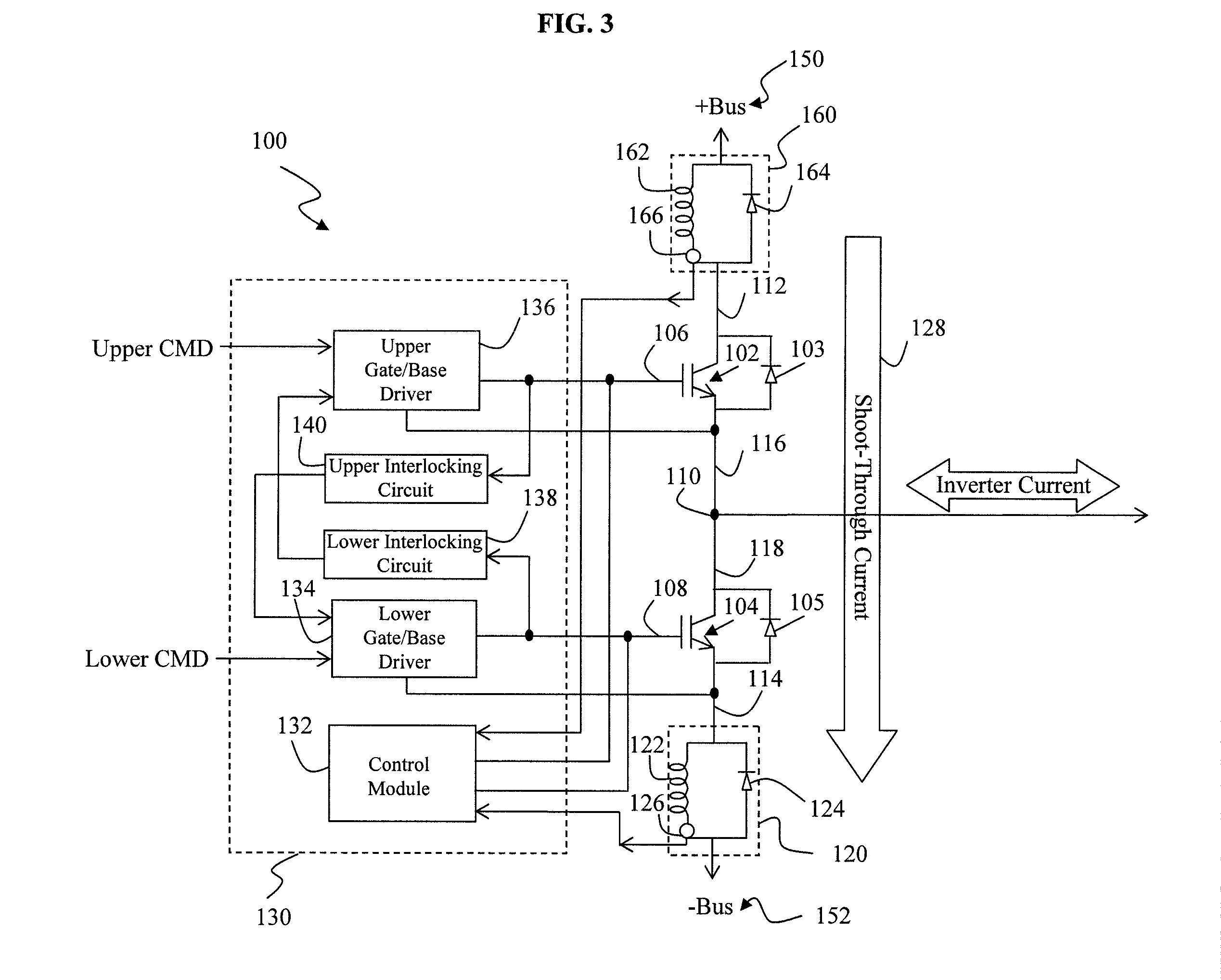
[0030]The invention features methods and systems for shoot-through protection. FIG. 3 illustrates a circuit diagram of a shoot-through protection circuit 100 according to some embodiments. The protection circuit 100 includes an upper transistor 102, a lower transistor 104, a control circuit 130, and delay modules 120 and 160. The transistors 102 and 104 can be, for example, bipolar junction transistors (BJTs) and / or field-effect transistors (FETs).

[0031]The upper transistor 102 includes a gate / base terminal 106, a collector / drain terminal 112, and an emitter / source terminal 116. The lower transistor 104 includes a gate / base terminal 108, a collector / drain terminal 118 and a source / emitter terminal 114. Both transistors 102 and 104 can be in parallel with diodes 103 and 105. The collector / drain terminal 112 of the upper transistor 102 is coupled to a positive terminal 150 of a DC power supply (not shown) via the upper delay module 160. The emitter / source terminal 114 of the lower tra...


PUM


Abstract

A switching apparatus includes a first transistor, a second transistor, a first circuit module, a first current sensor and a control circuit. The first transistor includes first, second and third terminals. The first terminal of the first transistor is coupled to a first power terminal. The third terminal of the first transistor includes a gate or base of the first transistor. The second transistor includes first, second and third terminals. The first terminal of the second transistor is coupled to a second power terminal. The second terminal of the second transistor is coupled to the second terminal of the first transistor. The third terminal of the second transistor includes a gate or base of the second transistor. The first circuit module includes an inductor in parallel with a diode. The first circuit module is connected between the first terminal of the second transistor and the second power terminal.

Description

FIELD OF THE INVENTION[0001]The invention relates generally to protecting circuit components against shoot-through current, and to apparatuses for and methods of protecting circuit components against shoot-through current.BACKGROUND OF THE INVENTION[0002]A two-switch circuit topology typically includes a pair of switching devices that are alternately operated. For example, a power inverter can include one or more branches coupled to a DC power source. Each branch can include a pair of switching devices that are alternately operated to connect the junction between the devices to the voltage of the power source, thereby producing an alternating output. Shoot-through currents can occur if both switching devices are turned on at the same time, which can damage and / or short circuit components of the circuit and degrade the output waveform.[0003]One method for minimizing shoot-thorough phenomenon involves the use of an interlock circuit to prevent both switching devices from being on simu...

Claims


Application Information

Patent Timeline
Patent Type & Authority Patents(United States)
IPC IPC(8): H02M3/337H02M1/38H03K17/082H02H3/08
CPCH03K2217/0036H02M3/337H02M1/38H03K17/0822H02M3/33573H02M3/33571
Inventor TRAN, KENTIAN, FENGCHEN, XING
Owner MKS INSTR INC
Why Eureka
Try Eureka