IGBT non-contact lifting electromagnet control system for non-rectifying transformer

A technology for lifting electromagnets and rectifier transformers, applied in electromagnets, electromagnetic circuit devices, etc., can solve problems such as overvoltage, and achieve the effects of saving purchase funds, light weight, and simple and convenient chain control

Inactive Publication Date: 2017-02-01
SHENYANG AEROSPACE UNIVERSITY
View PDF7 Cites 4 Cited by
  • Summary
  • Abstract
  • Description
  • Claims
  • Application Information

AI Technical Summary

Problems solved by technology

[0005] The invention provides a creative IGBT non-contact lifting electromagnet control system without a rectifier transformer, so as to solve the deficiencies in the prior art, thereby solving the overvoltage when the large inductance L current is turned off and other phenomena

Method used


Image

  • IGBT non-contact lifting electromagnet control system for non-rectifying transformer
  • IGBT non-contact lifting electromagnet control system for non-rectifying transformer
  • IGBT non-contact lifting electromagnet control system for non-rectifying transformer

Examples


specific Embodiment 1

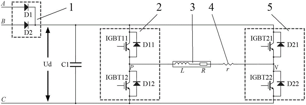
[0042] Specific embodiment 1: IGBT contactless lifting electromagnet control system without rectifier transformer, the main circuit includes diode module 1, insulated gate bipolar transistor module 12, insulated gate bipolar transistor module 25, capacitor C1, electromagnet 3 and shunt r4; the diode module 1 includes two diode elements, which are diode D1 and diode D2, and diode D1 and diode D2 are connected in parallel; the insulated gate bipolar transistor module 12 includes two IGBT elements, respectively IGBT11 and IGBT12, IGBT11 and IGBT12 are connected in series; the IGBT11 is connected in anti-parallel with a diode D11, the IGBT12 is connected in anti-parallel with a diode D12, and the insulated gate bipolar transistor module 25 includes 2 IGBT elements, respectively IGBT21 and IGBT22 ; IGBT21 and IGBT22 are connected in series, IGBT21 has a diode D21 in anti-parallel, IGBT22 has a diode D22 in anti-parallel,

[0043] One end of the insulated gate bipolar transistor mod...

specific Embodiment 2

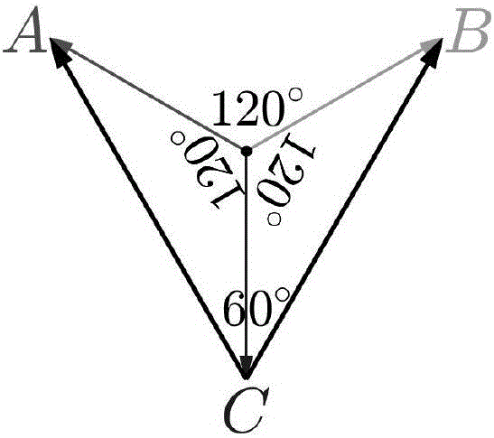
[0054] combine figure 2 As shown, connect the 380V three-phase alternating current U A , U B and U C In the access circuit, after being rectified by diodes D1, D2 and capacitor C1, a pulsating DC voltage U with a period of 20ms is obtained d , in the main circuit U will be C as the reference voltage, so U AC and U BC is the phase difference of 60°, the effective value is 380V AC, such as image 3 shown; if the energy storage effect of capacitor C1 is ignored, the effective value of the pulsating DC voltage rectified by diodes D1 and D2 As shown in formula (1), the waveform diagram is as follows Figure 4 shown;

[0055] U ¯ d = 2 2 π ∫ 0 2 π / 3 380 2 · s i n θ d θ = 3 ...


PUM


Abstract

Disclosed is an IGBT non-contact lifting electromagnet control system for a non-rectifying transformer. The IGBT non-contact lifting electromagnet control system comprises a main loop, wherein the main loop comprises a diode module, an insulated gate bipolar type transistor module 1, an insulated gate bipolar type transistor module 2, a capacitor C1, an electromagnet and a current divider r; the diode module comprises a diode D1 and a diode D2 which are connected in parallel; the insulated gate bipolar type transistor module 1 comprises an IGBT 11 and an IGBT 12 which are connected in series; the IGBT 11 is in anti-parallel connection with a diode D11 while the IGBT 12 is in anti-parallel connection with a diode D12; the insulated gate bipolar type transistor module 2 comprises an IGBT 21 and an IGBT 22 which are connected in series; the IGBT 21 is in anti-parallel connection with a diode D21 while the IGBT 22 is in anti-parallel connection with a diode D22; and one end of the insulated gate bipolar type transistor module 1 is connected with the capacitor C1 in parallel. By adoption of the IGBT non-contact lifting electromagnet control system, when the inductive current of the electromagnet is switched off, an electromagnetic overvoltage phenomenon generated at the two ends of the electromagnet can be eliminated without requiring a current-following element.

Description

technical field [0001] The invention belongs to a matching device of an electromagnet, in particular to an IGBT contactless lifting electromagnet control system without a rectifier transformer. Background technique [0002] At present, the commonly used control method for lifting electromagnets is the control method of thyristor positive and negative bridge, which adjusts the output voltage by changing the trigger angle of the thyristor, that is, the phase angle control method, such as figure 1 The circuit is composed of a rectifier transformer and two sets of thyristor fully controlled bridges, namely forward bridge A and reverse bridge B; The phase thyristor fully controlled bridge A or B rectifies and regulates the voltage to provide adjustable excitation DC voltage and demagnetization DC voltage for the electromagnet. When the forward bridge A is turned off and the reverse bridge B is turned off, the circuit provides the electromagnet with a forward excitation voltage o...

Claims


Application Information

Patent Timeline
Patent Type & Authority Applications(China)
IPC IPC(8): H01F7/06
CPCH01F7/064
Inventor 张太宁朱琳琳梁宵陈新禹
Owner SHENYANG AEROSPACE UNIVERSITY
Why Eureka
Try Eureka