Multifunction timepiece having fan shape moving hand train wheel and fan shape moving hand train wheel apparatus

a multi-functional timepiece and hand train technology, applied in the direction of visual indication, instruments, horology, etc., can solve the problems of large time period needed in the operation of working and integrating parts

Inactive Publication Date: 2006-06-15
SEIKO INSTR INC
View PDF11 Cites 6 Cited by
  • Summary
  • Abstract
  • Description
  • Claims
  • Application Information

AI Technical Summary

Benefits of technology

[0012] It is an object of the invention to realize an analog multifunction timepiece which is small-sized and constituted such that much time per

Problems solved by technology

However, the hairspring is used in the multifunction timepiece having the small hand moved in the fan shape of the background art and the

Method used


Image

  • Multifunction timepiece having fan shape moving hand train wheel and fan shape moving hand train wheel apparatus
  • Multifunction timepiece having fan shape moving hand train wheel and fan shape moving hand train wheel apparatus
  • Multifunction timepiece having fan shape moving hand train wheel and fan shape moving hand train wheel apparatus

Examples


first embodiment

(3)

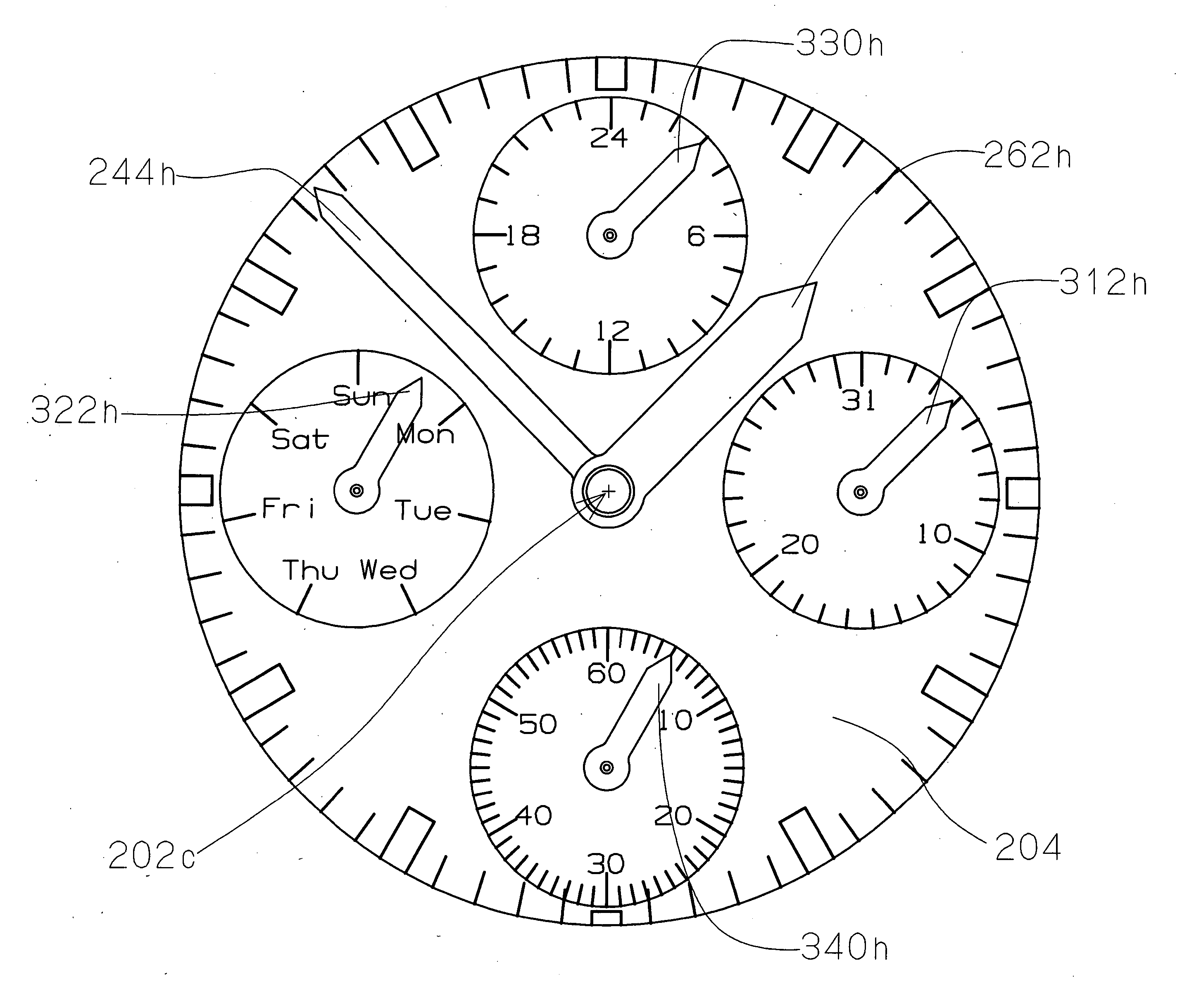
[0135] Next, a first embodiment of a multifunction timepiece of the invention will be explained. In the following explanation, a point in which the first embodiment of the multifunction timepiece of the invention differs from the above-described first basic mode will mainly be described. Therefore, the above-described explanation of the first basic mode will be applied to a portion which is not described below. A point in which the first embodiment of the multifunction timepiece of the invention differs from the first basic mode resides in a day display mechanism. That is, the first embodiment of the multifunction timepiece of the invention is characterized in providing a day hand of so-to-speak “retrograde type” capable of being moved in a fan shape.

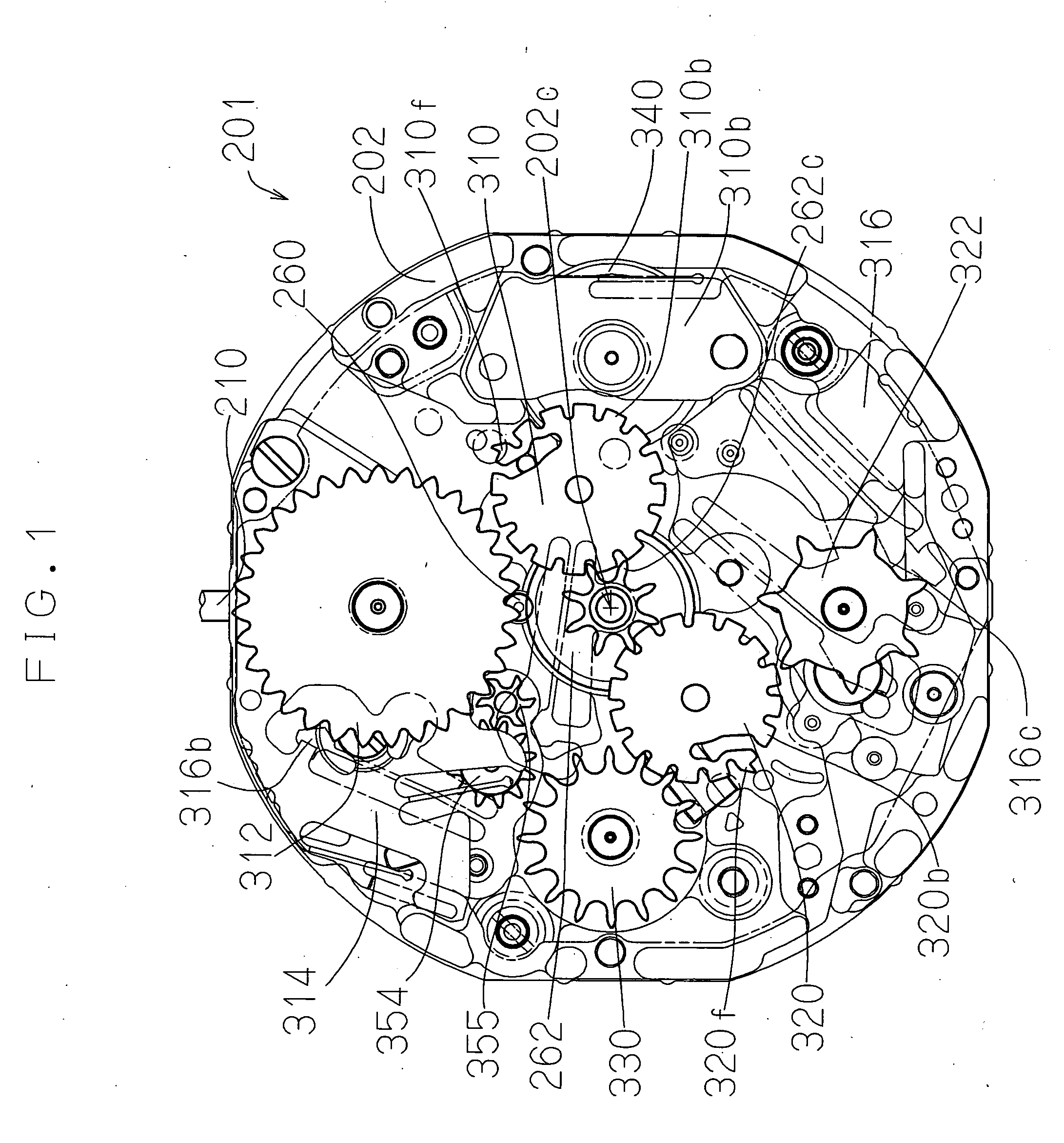
(3•1) Structure of Total of Movement:

[0136] In reference to FIG. 25 through FIG. 27, according to the first embodiment of the multifunction timepiece of the invention, a movement is constituted by an analog electronic timepiece. F...

second embodiment

(4)

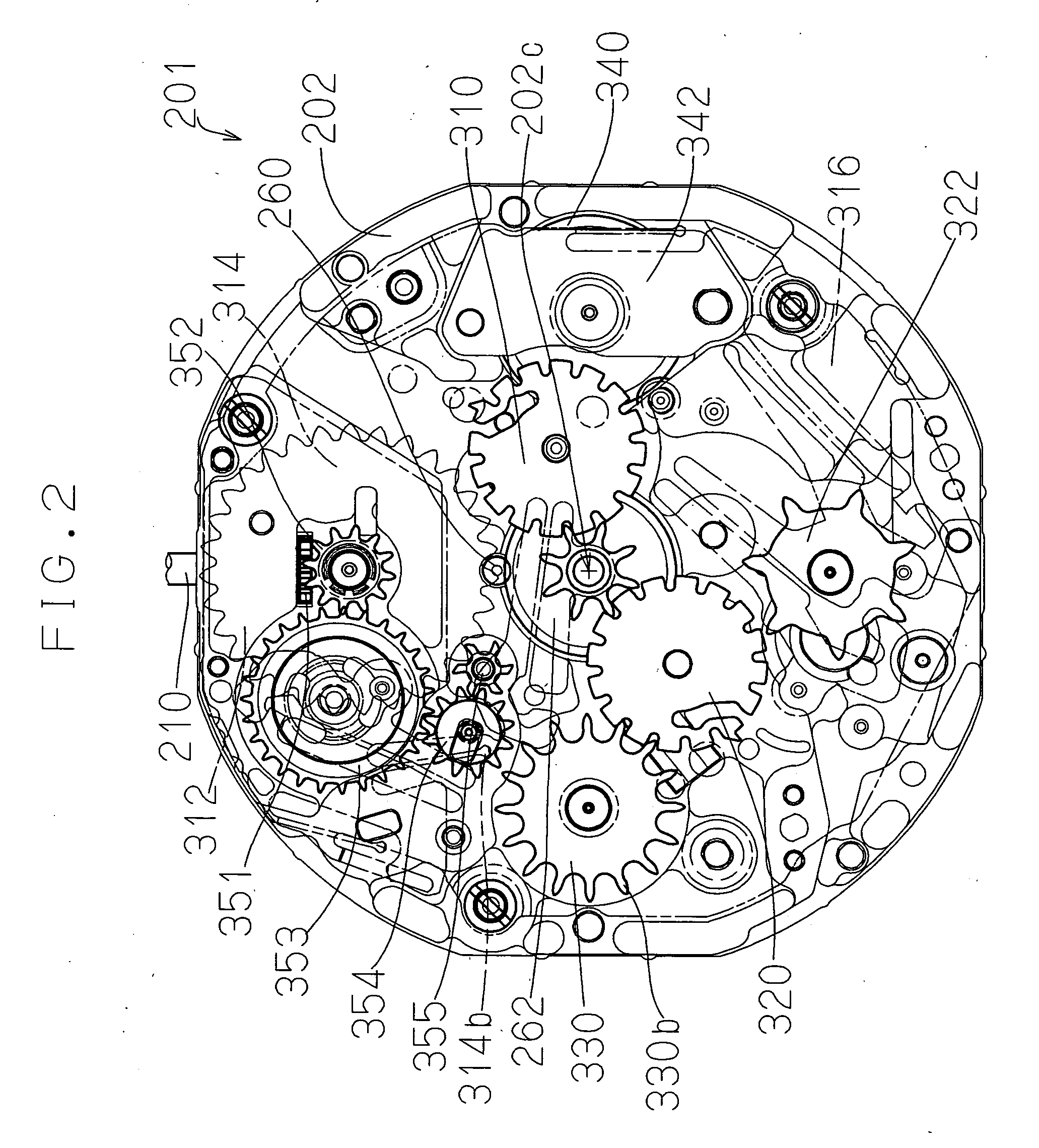
[0158] Next, a second embodiment of the multifunction timepiece of the invention will be explained. In the following explanation, a point in which the second embodiment of the multifunction timepiece of the invention differs from the above-described first embodiment will mainly be described. Therefore, the above-described explanation of the first embodiment will be applied to a portion which is not described below.

(4•1) Structure of Total of Movement:

[0159] In reference to FIG. 34, according to the second embodiment of the multifunction timepiece of the invention, a movement is constituted by an analog electronic timepiece. Further in details, the second embodiment of the multifunction timepiece of the invention is constituted by an analog timepiece (electric timepiece, electronic timepiece, mechanical timepiece) having a small hand capable of being moved to rotate at at least one portion in “2 o'clock direction”, “6 o'clock direction”, further, having a small hand capable of ...


PUM


Abstract

To realize a small-sized analog multifunction timepiece by adopting a fan shape moving hand mechanism which does not use a hairspring. A multifunction timepiece of the invention is provided with a day display mechanism for operating a small hand moving in a fan shape. The day display mechanism is provided with a day indicator driving wheel, a day jumper, a small day wheel for displaying calendar information, a hammer constituted to rotate based on rotation of a day indicator transmission wheel, and a day return spring for exerting a rotational force to the small day wheel. By bringing a cam contact portion of the hammer to a transmission cam outer periphery portion and exerting an elastic force to a return cam outer shape portion by a return spring portion of the day return spring, the small day wheel is constituted to be exerted with a rotational force in a constant direction.

Description

BACKGROUND OF THE INVENTION [0001] 1. Field of the Invention [0002] The present invention relates to a multifunction timepiece having a fan shape moving hand train wheel. Particularly, the invention relates to a multifunction timepiece having a fan shape moving hand train wheel which is small-sized and facilitated to fabricate and integrate a part in an analog multifunction timepiece having small hands for executing various displays. Further, the invention relates to a fan shape moving hand train wheel apparatus which is small-sized and facilitated to fabricate and integrate a part. [0003] 2. Description of the Prior Art (1) Explanation of Terminology: [0004] Generally, a machine body including a portion of driving a timepiece is referred to as “movement”. A state in which a movement is attached with a dial, hands is put into a timepiece case to constitute a finished product is referred to as “complete” of a timepiece. In both sides of a main plate constituting a base plate of a ti...

Claims


Application Information

Patent Timeline
IPC IPC(8): G04B19/00G04C17/00
CPCG04B19/24G04B19/241G04C17/00
Inventor HIRANO, KEIWATANABE, MAMORUTOKORO, TAKESHI
Owner SEIKO INSTR INC
Why Eureka
Try Eureka