Fan rotating blade for turbofan engine

a technology of rotating blades and turbofans, which is applied in the direction of machines/engines, mechanical equipment, liquid fuel engines, etc., can solve the problems of increased circumferential speed, increased engine weight, and increased so as to reduce the stress at the root of the leading edge part, increase the flow rate, and reduce the effect of stress

Active Publication Date: 2010-09-16
IHI CORP
View PDF12 Cites 56 Cited by
  • Summary
  • Abstract
  • Description
  • Claims
  • Application Information

AI Technical Summary

Benefits of technology

[0028]With the above-described configuration according to the invention, since the vertical hub portion on the hub side of the leading edge part is substantially perpendicular to the fan rotary shaft, a weight of the blade is smaller than a case in which the hub portion is inclined toward the upstream side, thereby particularly reducing a stress at the root of the leading edge part. Also, since a chord length is longer than a case in which the hub portion is inclined toward the downstream side, it is possible to increase a pressure ratio. Additionally, at the same time, when the chord length is long, a large flow is received on the hub side, thereby increasing a flow rate in the same engine front-surface area.
[0029]Also, since the outside of the backward inclined mid-span portion positioned at the mid-span is inclined backward with respect to the plane perpendicular to the fan rotary shaft, a blade center of gravity is more positioned on the downstream side than a case in which the outside is inclined forward (forward inclination), thereby particularly reducing a stress at the leading edge part on the hub side.
[0030]Also, since the outside of the forward inclined tip portion on the tip side is inclined forward, an inflow speed on the tip side is smaller than a case in which the outside is inclined backward (backward inclination), thereby reducing a loss of a shock wave.
[0031]Therefore, in a turbofan engine having a large bypass ratio, it is possible to increase an air flow rate of a fan first-stage rotating blade without enlarging the fan first-stage rotating blade and a diameter of a casing surrounding the fan first-stage rotating blade. Accordingly, since a bypass ratio is increased, it is possible to realize a decrease in fuel consumption and noise and to reduce a weight. Additionally, it is possible to more increase a pressure ratio on the hub side than the fan rotating blade according to the conventional art.

Problems solved by technology

However, in the above-described turbofan engine, a problem arises in that a fan first-stage rotating blade (an up-front fan) and an inner diameter of a casing surrounding the fan first-stage rotating blade are enlarged by enlarging the bypass ratio, and a weight of the engine is increased.
As described above, in the turbofan engine according to the conventional art, a problem arises in that the fan first-stage rotating blade (the up-front fan) and the inner diameter of the casing surrounding the fan first-stage rotating blade are enlarged by enlarging the bypass ratio, and the weight of the engine is increased.
Additionally, in the fan first-stage rotating blade according to the conventional art, for example, when a rotary speed is increased in order to increase an amount of air introduced from the outside, a circumferential speed increases too much, thereby causing a problem in that a loss of a shock wave excessively increases at a high flow

Method used


Image

  • Fan rotating blade for turbofan engine
  • Fan rotating blade for turbofan engine
  • Fan rotating blade for turbofan engine

Examples


Embodiment Construction

[0045]Hereinafter, a preferred embodiment of the invention will be described with reference to the drawings. Also, in the respective drawings, the same reference numerals are given to the same components and the repetitive description thereof will be omitted.

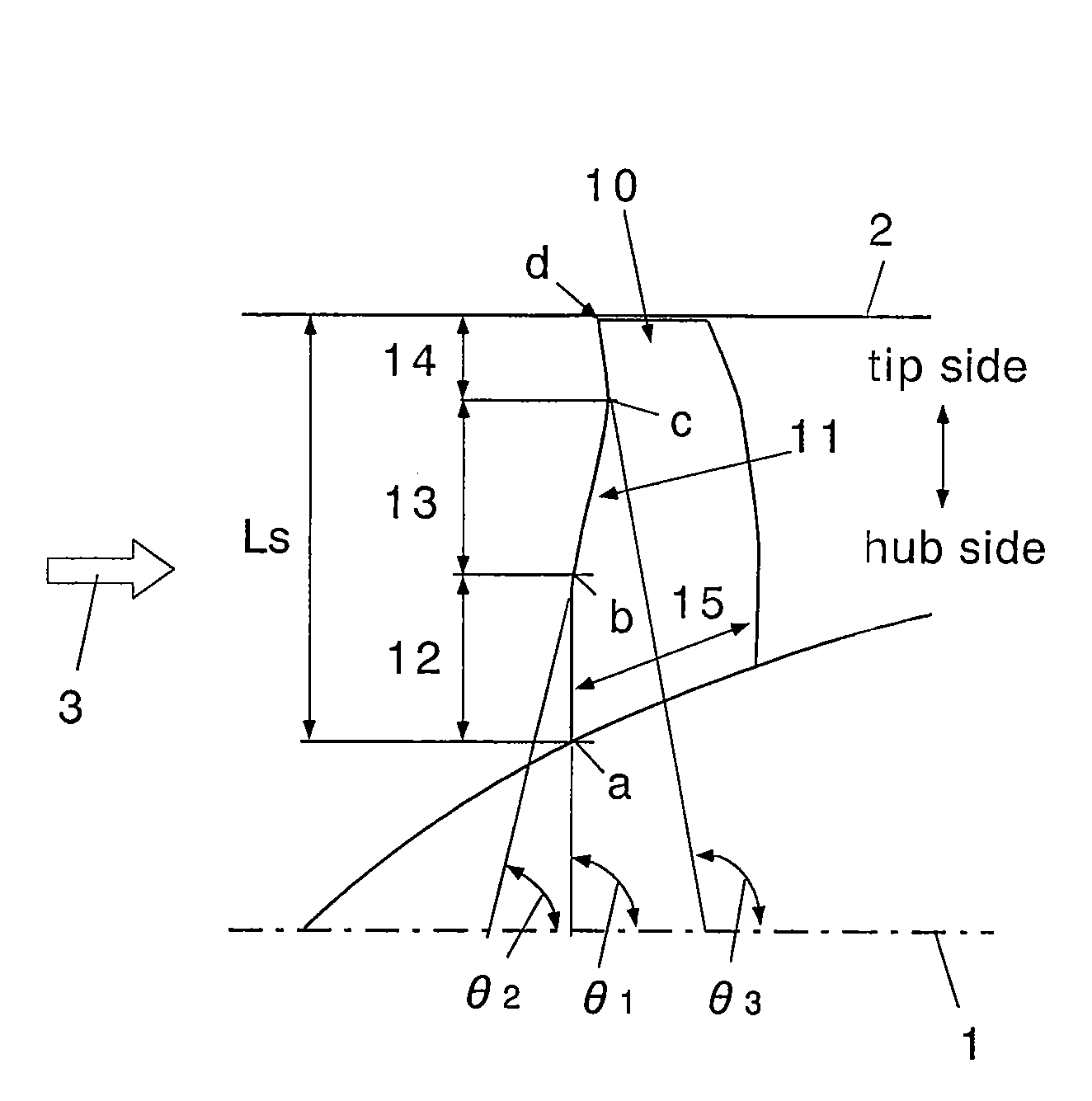
[0046]FIG. 3 is a configuration diagram showing a fan rotating blade for a turbofan engine according to the invention. In this drawing, Reference numeral 1 denotes an engine rotary shaft (fan rotary shaft), Reference numeral 2 denotes a casing inner diameter, and Reference numeral 3 denotes an intake air flow.

[0047]It is desirable that a fan rotating blade 10 according to the invention is a fan first-stage rotating blade, and a leading edge part 11 is formed by a vertical hub portion 12, a backward inclined mid-span portion 13, and a forward inclined tip portion 14.

[0048]The vertical hub portion 12 is positioned on the hub side so as to be substantially perpendicular to the fan rotary shaft 1.

[0049]In this example, it is desirab...


PUM


Abstract

[Object]
An object of the invention is to provide a fan rotating blade for a turbofan engine capable of increasing a bypass ratio by increasing an intake air flow rate without enlarging a diameter of a fan and an inner diameter of a casing and of realizing a decrease in weight of an engine as well as a decrease in fuel consumption and noise.
[Means for Solving the Problems]
A leading edge part 11 of a fan rotating blade 10 for taking air thereinto is provided with a vertical hub portion 12 positioned on the hub side so as to be substantially perpendicular to a fan rotary shaft, a backward mid-span portion 13 inclined toward the downstream side from the hub side to the mid-span portion, and a forward inclined tip portion 14 inclined toward the upstream side from the mid-span side to the tip portion.

Description

BACKGROUND OF THE INVENTION[0001]1. Technical Field of the Invention[0002]The present invention relates to a fan rotating blade for a turbofan engine.[0003]2. Description of the Related Art[0004]FIG. 1 is a schematic configuration diagram showing an aircraft engine 51 (a turbojet engine). As shown in this drawing, the turbojet engine is provided with a fan 52 for taking air thereinto, a compressor 53 for compressing the intake air, a combustor 54 for burning a fuel by the compressed air, a turbine 55 for driving the fan 52 and the compressor 53 by a combustion gas of the combustor 54, an after burner 56 for afterburning to increase a thrust, and the like.[0005]In the invention, a pressure ratio indicates a total downstream pressure / a total upstream pressure of a blade. Additionally, a bypass ratio indicates a value obtained by dividing a flow rate on a bypass side (air directly passing through a nozzle to be discharged to the outside of the engine) by a flow rate on a core side (a f...

Claims


Application Information

Patent Timeline
Patent Type & Authority Applications(United States)
IPC IPC(8): F01D5/14
CPCF01D5/141F04D29/324Y02T50/673Y02T50/671F04D29/384Y02T50/60
Inventor MUROOKA, TAKESHIMIZUTA, IKUHISA
Owner IHI CORP
Why Eureka
Try Eureka