
Oscillator coupled to an antenna and an application

a technology of oscillator and antenna, applied in the direction of measuring device, using reradiation, instruments, etc., can solve the problems of conflicting power consumption and availability, inability to provide power through radiated electric or magnetic field, and limited power supply used to power the transponder, etc., to achieve the effect of improving power efficiency

Active Publication Date: 2006-09-12
LINDELL KEVIN W
View PDF9 Cites 57 Cited by
  • Summary
  • Abstract
  • Description
  • Claims
  • Application Information

AI Technical Summary

Benefits of technology

[0019]An object of the invention is to provide a portable radar or radio frequency device with improved power efficiency. This will allow the power source to last for a longer period of time for a given sensitivity. This can also allow the power source to become smaller.
[0021]Yet another object of the invention is to reduce the parts complexity required to build an adaptable multi-function radio frequency frequency signal processing stage with the benefits of increased reliability and reduced cost.
[0037]The present invention solves the problems of the prior art with the use of an oscillator circuit as an amplification device with low power consumption to meet the above stated goals of providing a receiver with a long battery life, e.g., of six months. A device built according to the present invention with the same total gain as conventional technology will consume about 1 milliamp of current and will run many times longer.
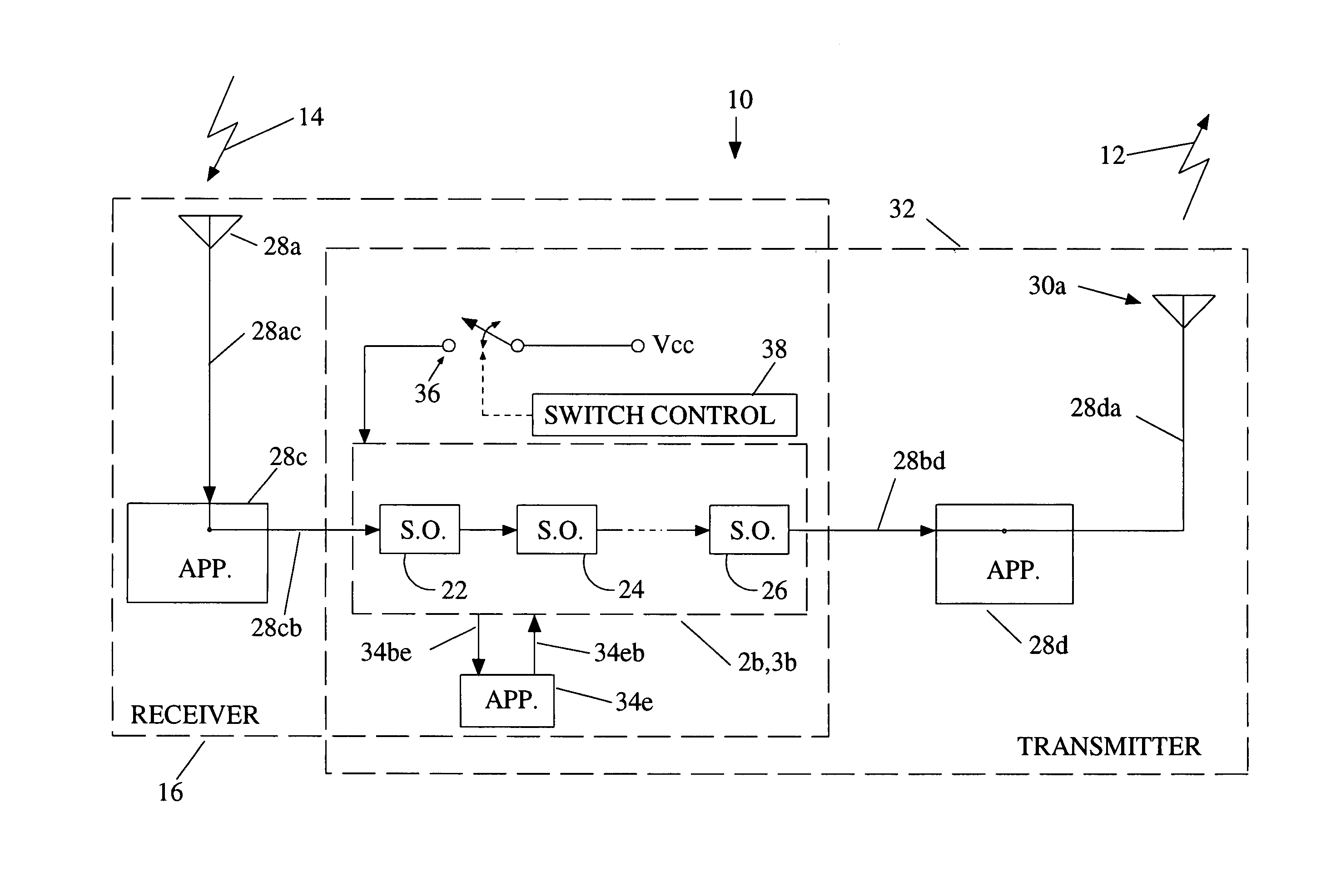
[0038]A certain type of oscillator, such as a synchronous oscillator (S.O.), can be employed in such a way as to behave as a sensitive receiver with filtering characteristics without the use of super heterodyning circuits that require the use of a local oscillator. According to the teachings of the present invention, an S.O. is very useful for the purpose of achieving good energy efficiency because it is not constantly biased. In other words, although the S.O. is constantly powered, it is not constantly consuming that power over each repetitive cycle. Moreover, a synchronous oscillator used as a receiver can turn-on and lock to incoming signals in less than 500 nanoseconds. Because of the fast lock time, the duty cycle of this type of receiver being turned on every 5 seconds is 500 nanoseconds / 5 seconds=1 e-7. Multiplying this duty cycle by a run time goal of about 7 days will allow such a receiver to run for several years. The objects of the present invention therefore could only be met with the technology according to the teachings hereof including a synchronous oscillator used as a receiver with power management. This is due in large part to the low inherent power consumption of the S.O. and its ability to become operational in a short amount of time. Since the teachings hereof result in a battery consumption that is so much lower than the prior art e.g. with the AA size batteries, a smaller battery size could be used, making the overall receiver and battery package smaller, which becomes highly desirable for certain applications.

Problems solved by technology

Transponders are usually required to work at ranges that make it impractical to provide power by means of a radiated electric or magnetic field.
The power supplies that are used to power the transponders are limited, meaning they contain or are able to supply only a limited amount of energy.
In certain cases the power consumption and availability also become conflicting requirements.
Providing more power to the interrogation signal to increase the range to the transponder will also provide no benefit if the interrogator is not sensitive enough to receive the transponder reply or the transponder is not powerful enough to respond back.
While excess battery power may be available at the interrogator, it may not be at the transponder.
However, the transmit burst may not be able to be reduced further in time without loss of transmitted information.
These amplifiers can consume most of the power needed to operate the unit.
Also, assuming a transponder application, a transmitter section or responding part of the device will consume additional power.
However, it such a circuit, the receive sensitivity is limited by the crystal detector sensitivity of approximately −50 dBm so the range is limited for a given interrogation power level.
These devices are known to use power management but they inherently consume a large amount of power to obtain a higher degree of availability and sensitivity.
If a constantly powered synchronous oscillator were to be used in a portable radar or radio device with a limited power supply such as a battery, the limited power supply would run down rather quickly.
Higher receiver gain will of course consume a proportionately higher amount of power.

Method used


Image

  • Oscillator coupled to an antenna and an application
  • Oscillator coupled to an antenna and an application
  • Oscillator coupled to an antenna and an application

Examples


Embodiment Construction

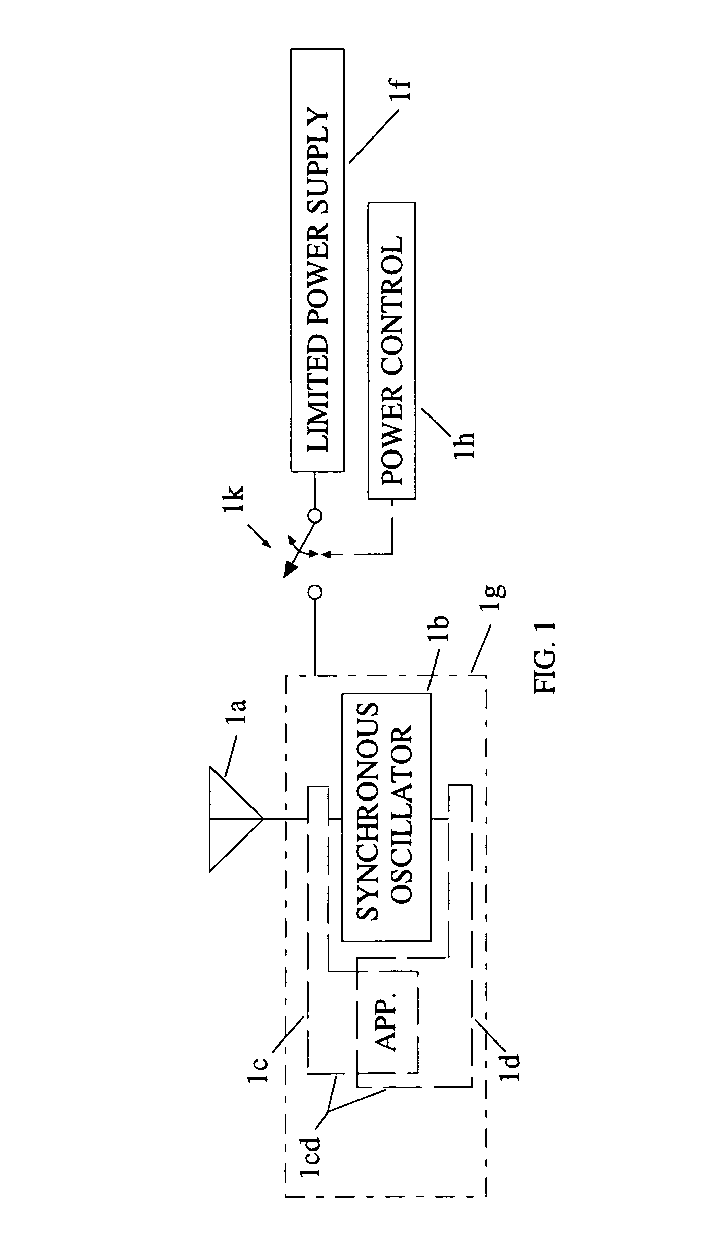
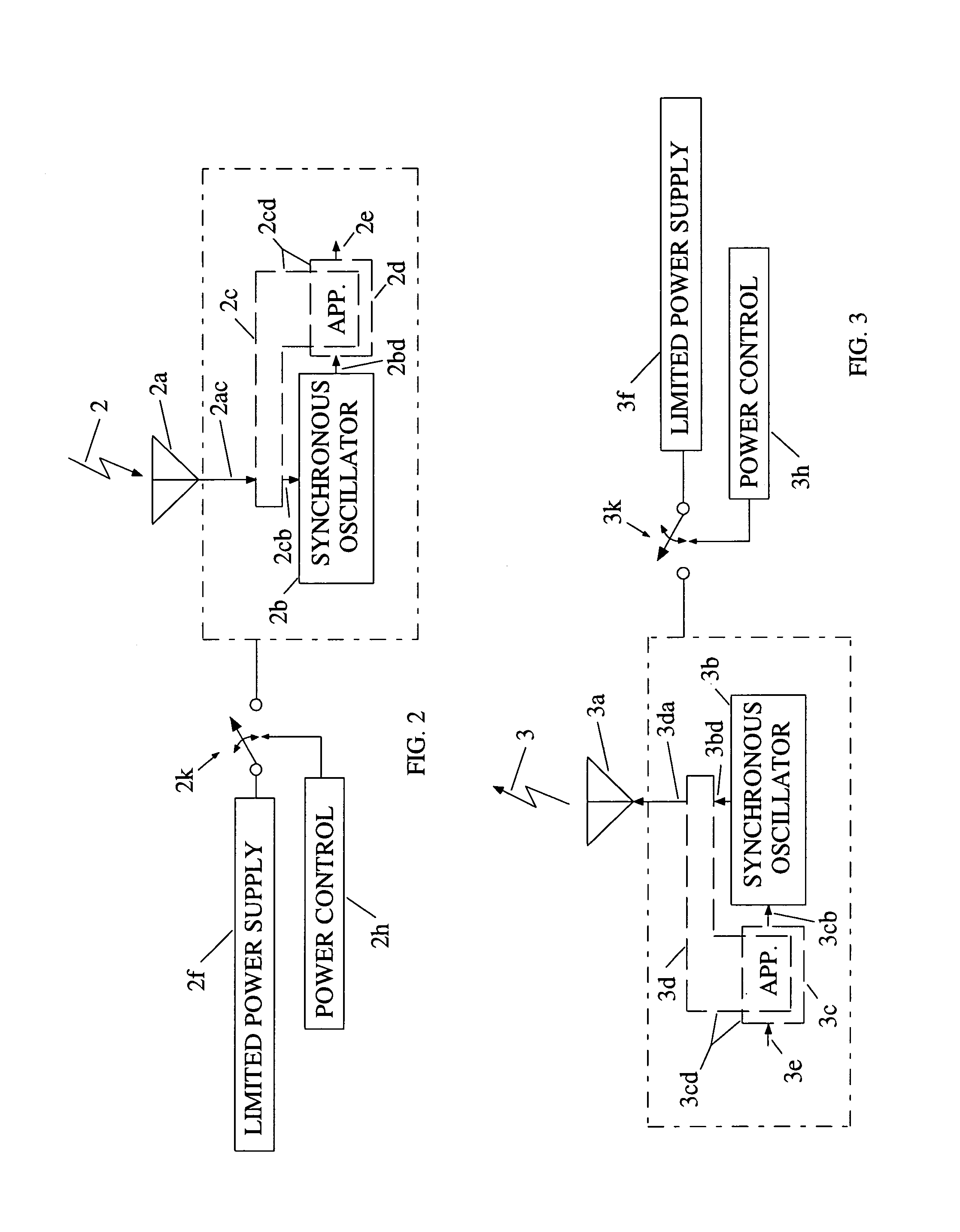
[0103]FIG. 1 shows a radio frequency device, according to the present invention, comprising an application 1cd coupled to an antenna 1a and to an oscillator which is preferably but not necessarily a synchronous oscillator (S.O.) 1b. The antenna and the S.O. work together with the application 1cd to carry out the ends of the application which can be various. According to the present invention, the application takes advantage of the signal processing properties of the S.O. The application 1cd is shown comprising two parts, one part 1c coupled between the antenna 1a and the S.O. and the other part 1d coupled to the S.O. on the other side of the S.O., but it should be realized that the application may comprise one or both parts 1c, 1d. Either or both application parts 1c, 1d can exist in a given embodiment and their functions can be separate or overlapping but nonetheless together constitute an application. The application therefore interfaces with an input, an output, or both the input...


PUM


Abstract

A radio frequency device has an antenna for capturing an incoming signal for processing by the device or for radiating an outgoing signal from the device and a signal processor having one or more synchronous oscillators responsive to an input signal for providing an amplified output signal without using much power. An application is a radio frequency (RF) transponder (tag) for receiving an RF signal from an interrogator includes a tag antenna for receiving the RF signal from the interrogator and a receiver section connected to the tag antenna wherein the receiver consumes a significantly lower amount of power than conventional receiver technologies by using one or more synchronous oscillators.

Description

CROSS REFERENCE TO RELATED APPLICATION[0001]This application claims priority from U.S. provisional application Ser. No. 60 / 445,338 filed Feb. 5, 2003TECHNICAL FIELD[0002]The present invention relates to a low power radio frequency device that is either a receiver that responds to an incoming radio frequency interrogation signal by providing an output signal or a transmitter that provides an outgoing radio frequency signal in response to an input signal, or a combination of both a receiver and a transmitter.BACKGROUND OF THE INVENTION[0003]A device of this type would include a radio frequency transponder. Such a device transmits a reply signal upon reception of an incoming signal. It usually includes a receiver, responsive to the incoming signal, for providing an amplified intermediate signal and a transmitter, responsive to the amplified intermediate signal, for transmitting the reply signal.[0004]For instance, present day radio frequency transponders are used to identify objects, p...

Claims


Application Information

Patent Timeline
IPC IPC(8): G01S13/74G01S13/00
CPCG01S13/767
Inventor LINDELL, KEVIN W
Owner LINDELL KEVIN W
Learn More