Switch connector

Inactive Publication Date: 2006-06-15
HON HAI PRECISION IND CO LTD
View PDF4 Cites 41 Cited by
  • Summary
  • Abstract
  • Description
  • Claims
  • Application Information

AI Technical Summary

Benefits of technology

[0008] An object of the invention is to provide a switch connector w

Problems solved by technology

However, the purchase cost of such resilient material is high.
During practical operation, a problem raises that the disconnect between the movable terminal and the fixed terminal is incom

Method used


Image

  • Switch connector
  • Switch connector
  • Switch connector

Examples


Example

[0018] Reference will now be made to the drawing figures to describe the present invention in detail.

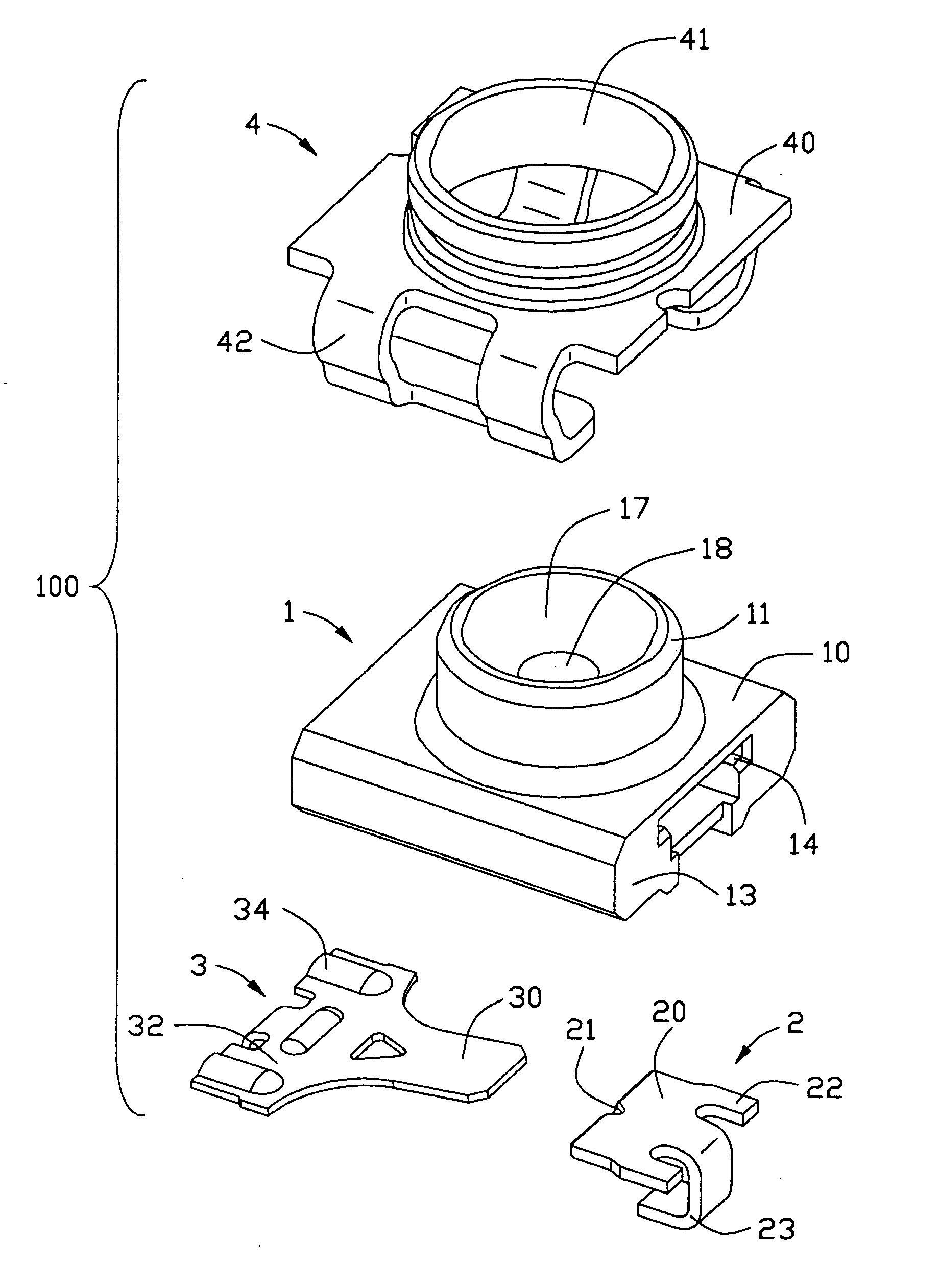
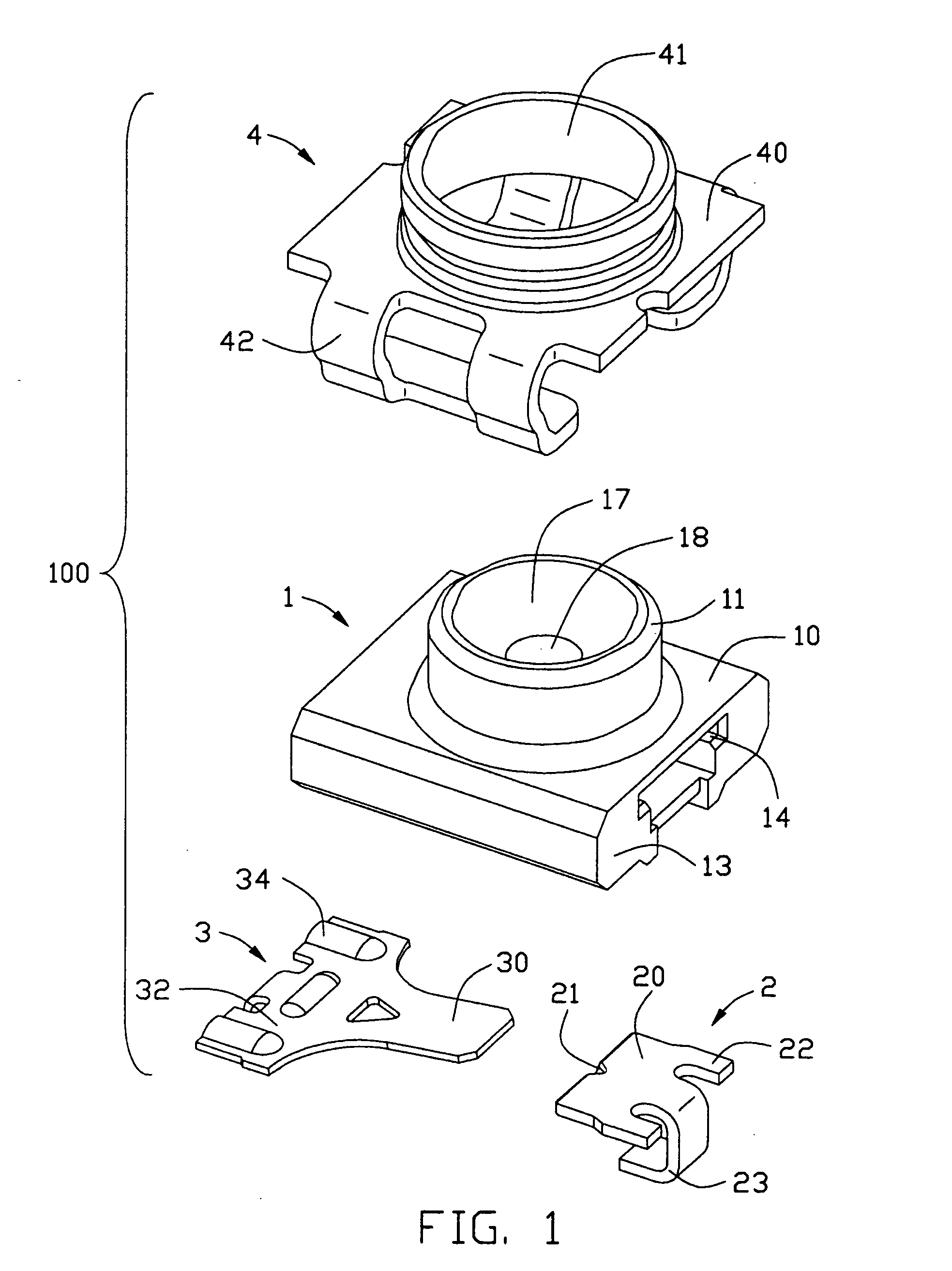
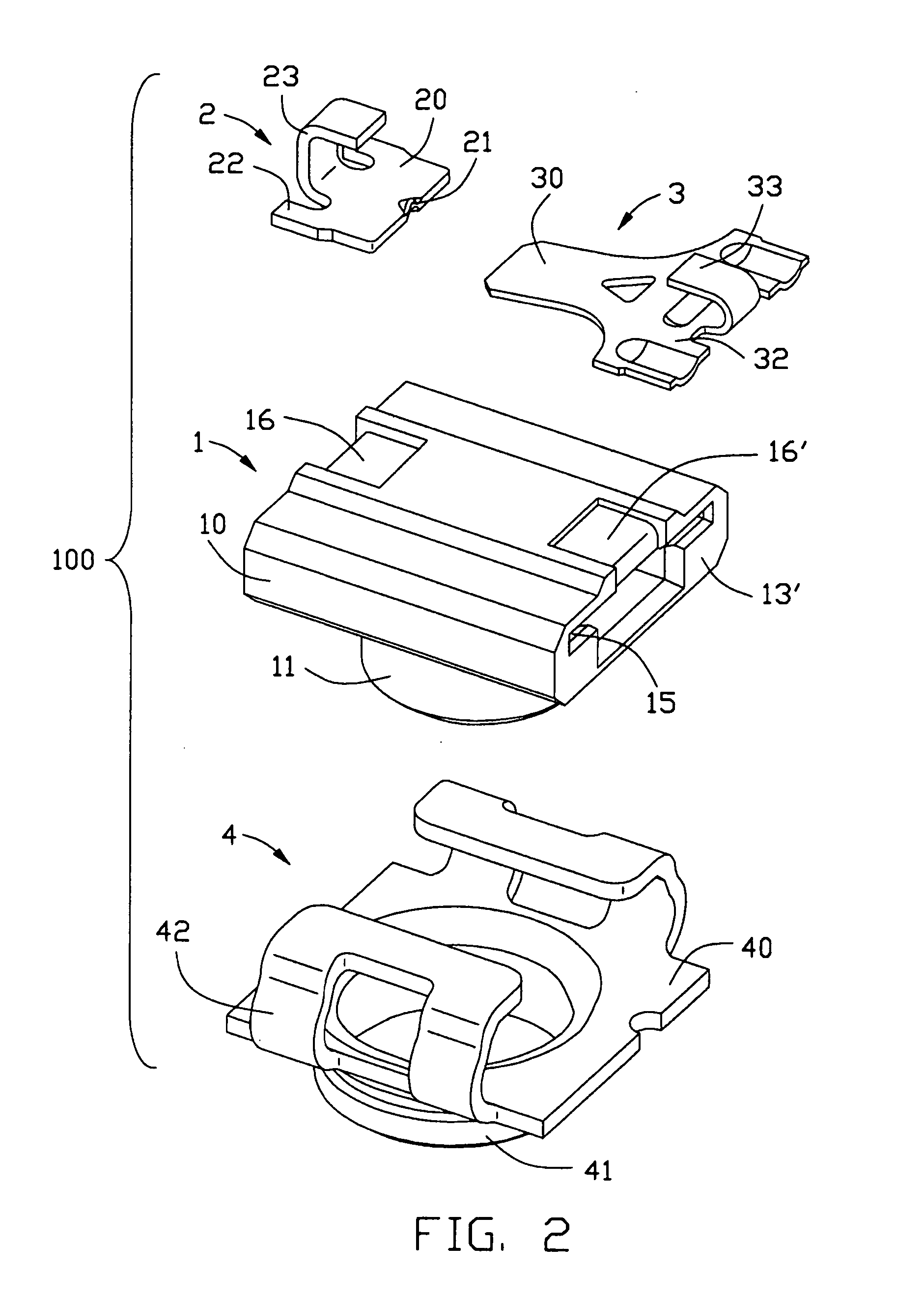
[0019] Referring to FIGS. 1, 2, 3, and 4, a switch connector 100 comprises a insulative housing 1, a fixed terminal 2, a switch terminal 3 and a shielding 4.

[0020] The insulative housing 1 comprises a base portion 10 having a cuboid shape and a cylindrical introduction portion 11 extending upwardly and perpendicularly from a approximate central portion on an upper surface of the base portion 10. The base portion 10 comprises a pair of lateral walls 13 and 13′, a hollow portion 12 passed through the lateral walls 13 and 13′, a pair of fixing slots 14 and 15 provided at a inside surface of the hollow portion 12 which are respectively extends from the lateral walls 13 and 13′, and a pair of notches 16 and 16′ defined on the bottom of the opposite two lateral walls 13 and 13′ of the cuboid base portion 10. The cylindrical introduction portion 11 defines an inner wall 17 having a cone s...


PUM


Abstract

A switch connector includes an insulative housing (1), a fixed terminal (2), a switch terminal (3) and a shielding (4). The insulative housing has a base portion (10) defining a hollow portion (12) and a pair of notches (16, 16′) on the bottom thereof, and a cylindrical introduction portion (11) upwardly extending from the base portion. The fixed terminal has a pair of first fixed portions (22) retained in the hollow portion and a U-shaped portion (23) retained in one of the pair of notches. The switch terminal has a second fixed portion (32) retained in the hollow portion and a U-shaped portion (33) retained in another notch. The shielding encloses the cylindrical introduction portion and the base portion of the insulative housing. An electrical connection between the fixed terminal and the switch terminal is obtained by a contact at a point.

Description

BACKGROUND OF THE INVENTION [0001] 1. Field of the Invention [0002] The present invention relates to a switch connector, and more particularly to a radio frequency switch connector for sensitively switching electrical signal. [0003] 2. Description of the Prior Art [0004] Nowadays, a switch connector having a signal-switching circuit is widely used in mobile electrical devices. The conventional switch connector commonly comprises an insulative housing, a shielding enclosing the insulative housing, and a fixed terminal and a movable terminal, both of which are retained in the insulative housing, and in their normally closed state, contact with one another. When a mating connector perpendicularly inserts into the conventional switch connector, an end of the movable terminal disconnects from the fixed terminal under a press force. [0005] Such a switch connector is disclosed in U.S. Pat. No. 6,783,374. The movable terminal includes a movable contact portion which is configured to have a ...

Claims


Application Information

Patent Timeline
IPC IPC(8): H01R29/00
CPCH01R12/57H01R24/46H01R2103/00
Inventor CHEN, KUN HUA
Owner HON HAI PRECISION IND CO LTD
Why Eureka
Try Eureka