Viscoelastic surfactant rheology modification

Active Publication Date: 2006-06-15
SCHLUMBERGER TECH CORP
View PDF22 Cites 26 Cited by
  • Summary
  • Abstract
  • Description
  • Claims
  • Application Information

AI Technical Summary

Benefits of technology

[0006] One embodiment is an oilfield treatment method consisting of preparing and injecting down a well a fluid containing a viscoelastic surfactant selected from zwitterionic, amphoteric, and cationic surfactants and mixtures of those surfactants, and a rheology enhancer in a concentration sufficient to shorten the shear recovery time of the fluid,

Problems solved by technology

For example, such materials may be beneficial at some concentrations and harmful (lower viscosity, reduced stability, greater shear sensitivity, longer rehealing times) at others.
In particular, many VES fluid systems exhibit long viscosity

Method used


Image

  • Viscoelastic surfactant rheology modification
  • Viscoelastic surfactant rheology modification
  • Viscoelastic surfactant rheology modification

Examples


example 1

[0046] The table below shows the shear recovery times observed when various amounts of WD200 were added to four surfactant systems. In these experiments, approximately 200 mL of already-mixed VES fluid was sheared at no less than 10,000 rpm for no less than 30 seconds and no more than 1 minute in a 1 L Waring blender. The shearing was stopped and timing was begun. The fluid was poured back and forth between a beaker and the blender cup and the fluid recovery was characterized by two times, referred to as the initial and final recovery times; both were estimated by visual observation. The initial fluid recovery time was the time at which fluid “balling” occurred (when the fluid showed the first signs of elasticity as indicated by the fluid taking a longer time to achieve a flat surface in the receiving beaker when poured). The final fluid recovery time was the time at which fluid “lipping” occurred. The fluid “lips” when inclining the upper beaker or cup containing the fluid does not...

example 2

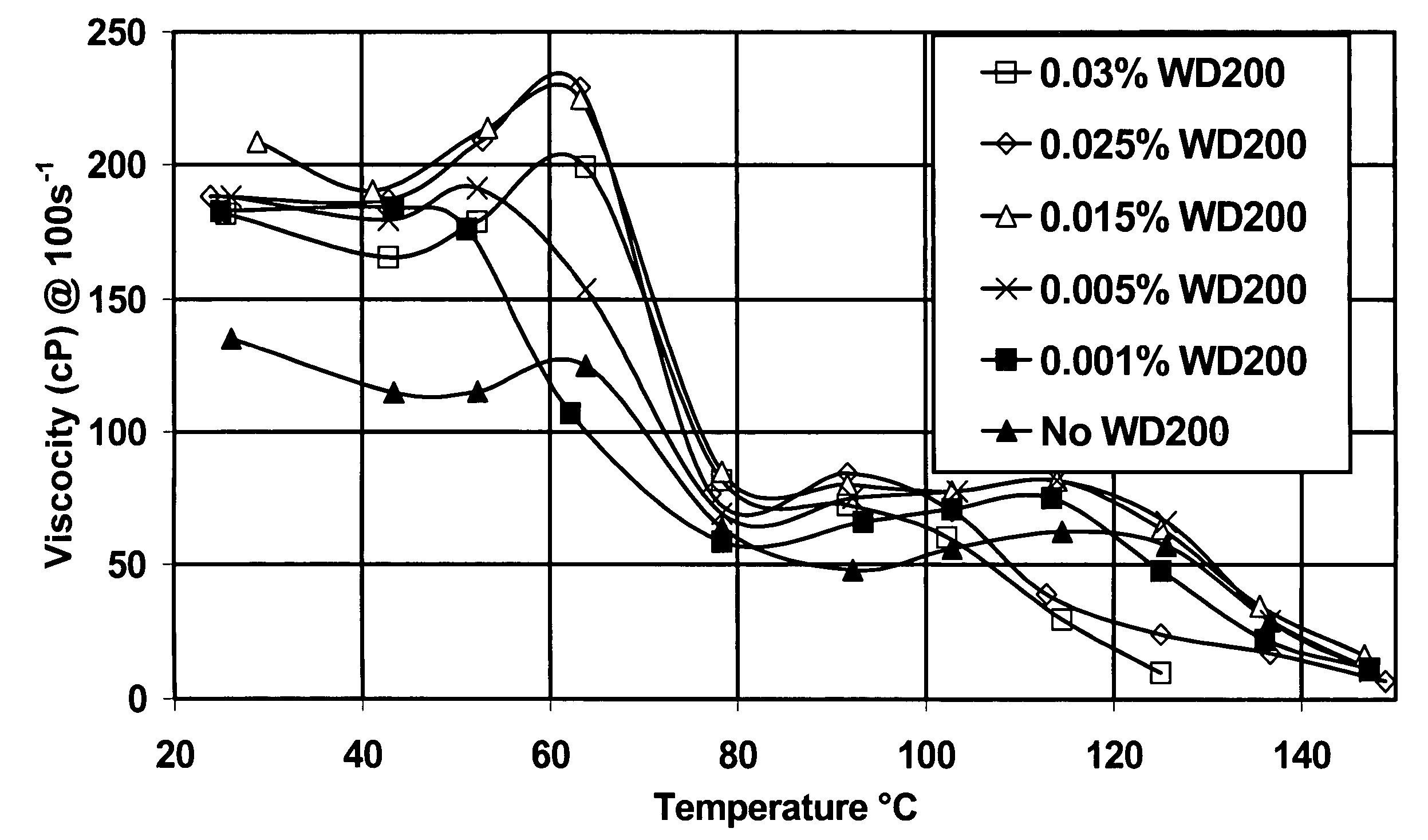
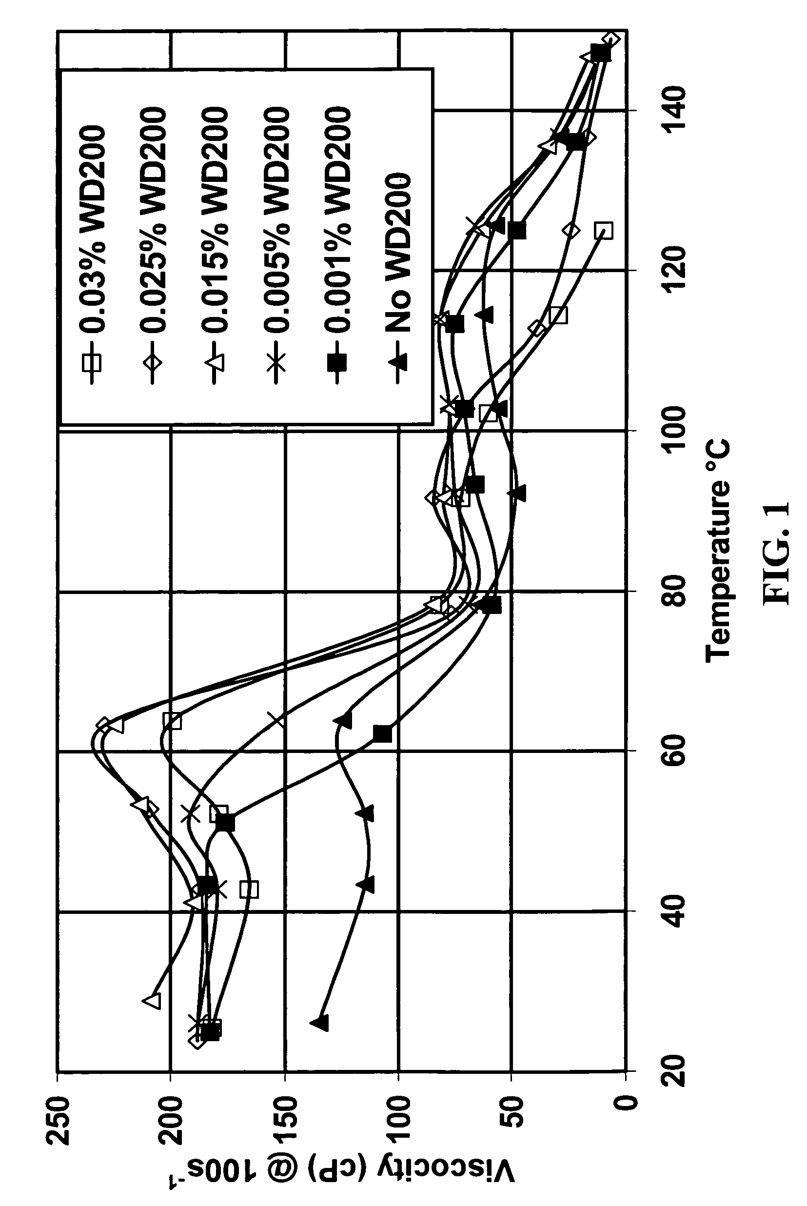
[0047] In addition to dramatically shortening shear recovery times at very low concentrations, the rheology enhancer of the invention also increases fluid system viscosity. Varying amounts of WD200 were added to fluids made with 4.5% of as-received surfactant concentrate Zw A without added salt. The viscosity measured with a Fann 50 at 100 sec−1 was measured at various temperatures. The results are shown in FIG. 1. At low temperatures, the viscosity was increased by all concentrations of WD200 tested. At higher temperatures, the higher WD200 concentrations lowered the viscosity (although they still shortened shear recovery time). For this concentration of this surfactant, about 0.015% of this rheology enhancer is optimal for increasing the viscosity over the entire temperature range. For other surfactant / rheology enhancer combinations and other surfactant concentrations, the optimal rheology enhancer concentration may be different. Similarly, if optimization at a certain temperature...

example 3

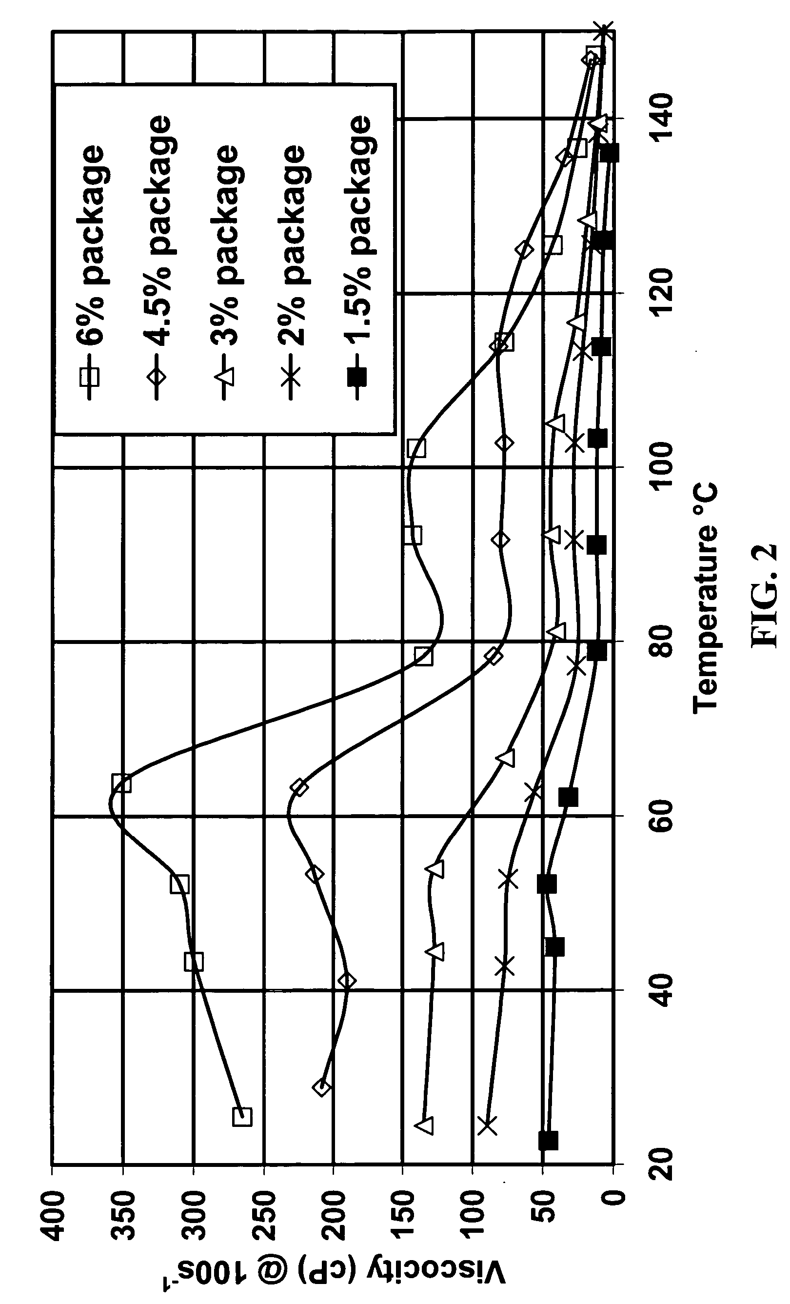
[0048] Because the rheology enhancer of the invention is suitable over a broad range of conditions, it is advantageous to prepackage a concentrate containing a viscoelastic surfactant and a rheology enhancer (or more than one of each) at a fixed concentration ratio. FIG. 2 shows the effect of varying the total concentration of one such package (as-received Zw A with WD200 added so that the ratio of surfactant to WD200 is 300) at varying concentrations.


PUM

PropertyMeasurementUnit
Fractionaaaaaaaaaa
Fractionaaaaaaaaaa
Fractionaaaaaaaaaa

Abstract

A method for shortening the shear recovery time of cationic, zwitterionic, and amphoteric viscoelastic surfactant fluid systems by adding an effective amount of an amphiphilic polymeric rheology enhancer containing at least one portion that is a partially hydrolyzed polyvinyl ester or partially hydrolyzed polyacrylate. The rheology enhancer also increases fluid viscosity and very low rheology enhancer concentration is needed. Preferred surfactants are betaines and quaternary amines. The fluids are useful in oilfield treatments, for example fracturing and gravel packing.

Description

CROSS REFERENCE TO RELATED APPLICATION [0001] This application is a Continuation in Part of prior copending application Ser. No. 11 / 012,446, filed Dec. 15, 2004, entitled “Viscoelastic Surfactant Rheology Modification”.BACKGROUND OF THE INVENTION [0002] The invention relates to rheology enhancers for viscoelastic surfactant fluid systems (VES's). More particularly it relates to selection and optimization of rheology enhancers for fluid systems to be used over broad ranges of salinity and temperature. Most particularly it relates to rheology enhancers to shorten shear recovery times and increase the viscosity of VES's for use in oilfield treatment fluids. [0003] Certain surfactants, when in aqueous solution, form viscoelastic fluids. Such surfactants are termed “viscoelastic surfactants”, or “VES's”. Other components, such as additional VES's, co-surfactants, buffers, acids, solvents, and salts, are optional or necessary (depending upon the specific VES fluid system used) and perform...

Claims


Application Information

Patent Timeline
IPC IPC(8): C11D1/10
CPCC09K8/602C09K8/68C09K8/88C09K2208/30C11D1/10
Inventor CHEN, YIYANABAD, CARLOS
Owner SCHLUMBERGER TECH CORP
Why Eureka
Try Eureka