Method and apparatus for energy recovery in an environmental control system

a technology of environmental control system and energy recovery, which is applied in the direction of domestic cooling apparatus, instruments, heating types, etc., can solve the problems of increasing heat transfer from the system, exacerbated energy loss, and one potential source of energy saving that has not yet been fully exploited

Inactive Publication Date: 2006-06-22
ELUTIONS
View PDF93 Cites 50 Cited by
  • Summary
  • Abstract
  • Description
  • Claims
  • Application Information

AI Technical Summary

Problems solved by technology

One potential source of energy savings has thus far not been fully exploited.
This energy loss is exacerbated by the fact that a correctly sized HVAC unit will operate at full capacity only on the hottest or coldest days of the year.
This overcapacity results in increased heat transfer from the system through ducting and other mechanical components of the HVAC system.
Attempts to recover this escaping energy have thus far been limited.
Although these systems do decrease energy waste somewhat, operator comfort is sacrificed to a degree which can be unacceptable.
For one thing, existing systems are not responsive to changes in external conditions which cause changes in the energy needs of the controlled space.
Thus, a fixed duty cycle will not be appropriate for optimally satisfying all calls for heating or cooling.
In these cases, the controlled space may require an unacceptably long time to heat or cool to a given thermostat setpoint, leaving the occupants uncomfortable for an extended period.
Furthermore, HVAC cycling during periods of high demand for heating or cooling may cause noticeable fluctuations in the temperature of the controlled space.
In addition to these factors, existing systems do not adequately provide for humidity control.
No presently available system, however, reduces HVAC energy consumption without serious consequences to operator comfort resulting from temperature swings and higher humidity levels.

Method used


Image

  • Method and apparatus for energy recovery in an environmental control system
  • Method and apparatus for energy recovery in an environmental control system
  • Method and apparatus for energy recovery in an environmental control system

Examples


Embodiment Construction

[0026] Preferred embodiments of the present invention will now be described with reference to the accompanying Figures, wherein like numerals refer to like elements throughout. The terminology used in the description presented herein is intended to be interpreted in its broadest reasonable manner, even though it is being utilized in conjunction with a detailed description of certain specific preferred embodiments of the present invention. This is further emphasized below with respect to some particular terms used herein. Any terminology intended to be interpreted by the reader in any restricted manner will be overtly and specifically defined as such in this specification.

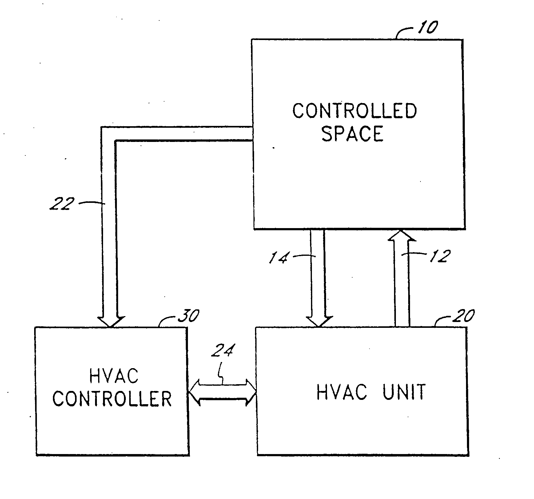
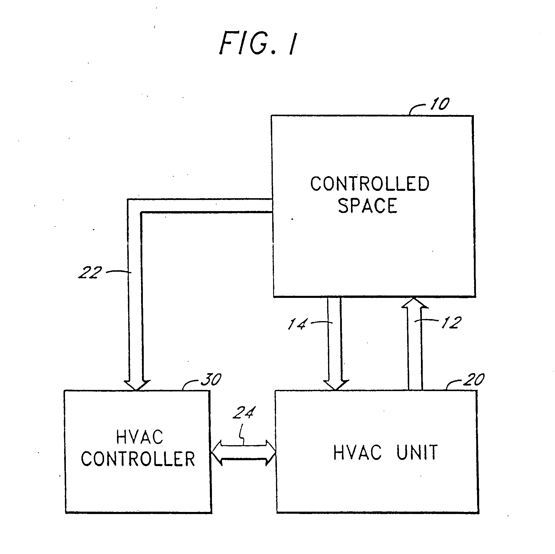
[0027] Referring now to FIG. 1, an environmental control system according to some aspects of the present invention is illustrated. A controlled space 10 receives heated and / or cooled air from a heating, ventilation and air conditioning (HVAC) unit 20. The controlled space may be an automobile interior, an office bu...


PUM


Abstract

Control apparatus for an environmental control system comprises input circuitry receiving environmental information and output circuitry for controlling an HVAC system. Processing circuitry in the controller configures the output circuitry based at least in part on the signals received on the input circuitry. Information about the status of the HVAC system may be transferred to system administrators using a wireless link.

Description

CROSS REFERENCE TO RELATED APPLICATIONS [0001] This application is a continuation of and claims priority to U.S. patent application Ser. No. 10 / 688,106, filed on Oct. 17, 2003, which is a continuation of U.S. patent application Ser. No. 10 / 268,070, filed on Oct. 7, 2002; which is a divisional of U.S. patent application Ser. No. 09 / 746,213, filed on Dec. 22, 2000, now U.S. Pat. No. 6,474,084; which is a continuation of U.S. patent application Ser. No. 09 / 351,974, filed on Jul. 12, 1999, now U.S. Pat. No. 6,176,436 issued on Jan. 23, 2001; which is a continuation of U.S. patent application Ser. No. 08 / 933,871, filed on Sep. 19, 1997, now U.S. Pat. No. 6,062,482 issued on May 16, 2000. The contents of U.S. patent application Ser. Nos. 10 / 268,070, 09 / 746,213, 09 / 351,974 and 08 / 933,871 are hereby incorporated by reference in their entireties.BACKGROUND OF THE INVENTION [0002] 1. Field of the Invention [0003] The present invention relates to controllers for heating, ventilation, and air c...

Claims


Application Information

Patent Timeline
Patent Type & Authority Applications(United States)
IPC IPC(8): F24F3/14F25D17/04F24F11/00
CPCF24F11/006F24F2011/0064F24F2011/0068F24F2011/0093G05D23/1919F24F11/30F24F11/62F24F11/65F24F11/56F24F11/39
Inventor GAUTHIER, DALE A.COVERT, GUY D.
Owner ELUTIONS
Why Eureka
Try Eureka