Low profile illumination for direct part mark readers

a reader and low-profile technology, applied in the field of symbol readers, can solve the problems of difficult reading of symbols printed on labels, high-angle bright field illumination may not be appropriate, and difficult to compare symbols printed directly on parts or components

Inactive Publication Date: 2006-06-22
COGNEX TECH & INVESTMENT
View PDF99 Cites 148 Cited by
  • Summary
  • Abstract
  • Description
  • Claims
  • Application Information

AI Technical Summary

Benefits of technology

[0012] The integrated optical transmitter has a transparent window to provide a path for reflected illumination into the imager module,

Problems solved by technology

Symbols marked directly on a part or component are often difficult to read in comparison to symbols printed on labels.
When a symbol or mark is etched

Method used


Image

  • Low profile illumination for direct part mark readers
  • Low profile illumination for direct part mark readers
  • Low profile illumination for direct part mark readers

Examples


Embodiment Construction

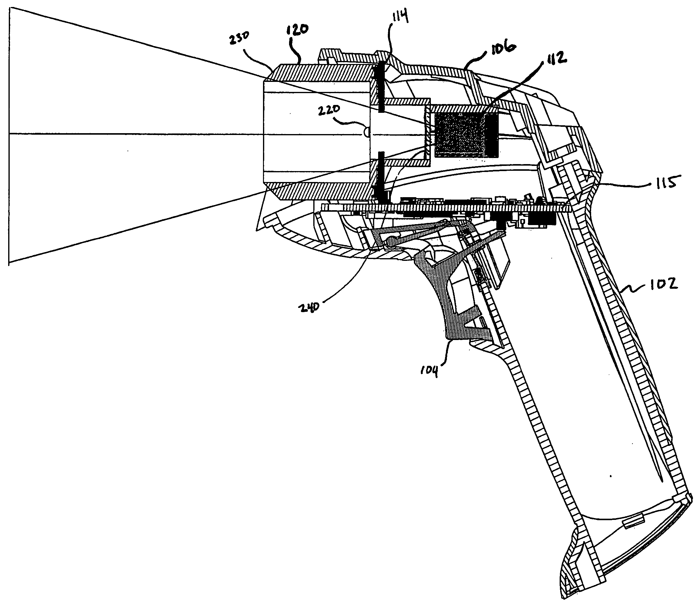
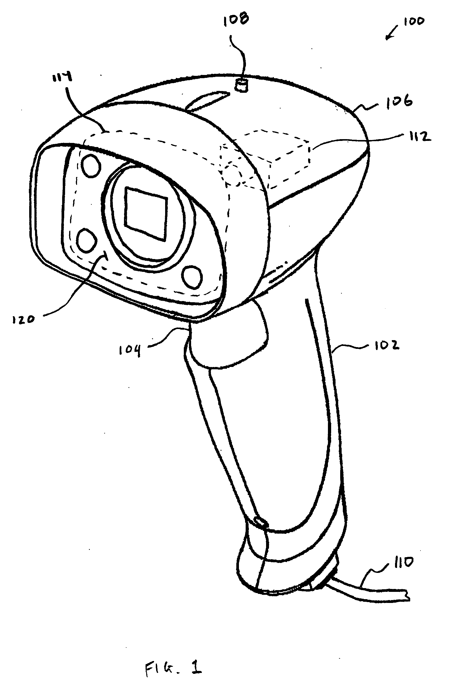
[0030]FIG. 1 shows an illustrative industrial mark reader 100 adapted for handheld operation, of the type that acquires an image of a mark or symbol, such as a one-dimensional or two-dimensional bar code, or data matrix symbol. An internal processor (not shown) performs an analysis of the acquired image, and decodes the mark or symbol to provide a character string of the encoded information.

[0031] The reader 100 shown in FIG. 1 has a grip portion 102 and a trigger 104 that can be actuated by a finger of the user to initiate the image acquisition and decoding function. A housing 106 contains an imager 112 (shown in phantom) that is connected to a processor (not shown). A status illuminator 108 provides visual indication of the status of the reader, such as to indicate a successful decode of an acquired image of a mark. A tether cord 110 provides electrical power to the reader 100, as well as a communication transmission path for the decoded character string of the encoded informatio...


PUM


Abstract

An industrial reader is provided with an image formation system that is particularly adapted to read bar codes and two-dimensional symbols marked directly on objects. The image formation system includes illumination sources and illumination transmissive components that produce a combination of bright field and dark field illumination.

Description

BACKGROUND OF THE INVENTION [0001] 1. Field of the Invention [0002] This invention relates to the field of symbology readers used to read symbols marked directly on objects. Symbology readers of this type, commonly known as direct part mark readers, are an extension of hand-held and fixed-mount image-based symbology readers. A direct part mark reader requires a unique image formation system to produce an image of a symbol that can be successfully and consistently decoded. [0003] 2. Description of the Related Art [0004] Two-dimensional symbols are used for most direct part marking applications because such symbols can encode a sufficient number of characters while maintaining a relatively compact size. Error correction schemes are typically included in most two-dimensional symbologies, to improve the readability. The two-dimensional symbols are marked directly on the part or component using various methods, depending upon the material composition, part application, and environmental ...

Claims


Application Information

Patent Timeline
IPC IPC(8): G06K7/10
CPCG06K7/10732
Inventor NUNNINK, LAURENS
Owner COGNEX TECH & INVESTMENT
Why Eureka
Try Eureka