Mechanical self-cleaning probe via a jiggler

a technology of mechanical self-cleaning and probes, which is applied in the direction of lighting and heating apparatus, process and machine control, instruments, etc., can solve the problems of false probe readings, dry firing of the boiler, flooding of the boiler, etc., and achieve the effect of reducing or eliminating the need

Active Publication Date: 2006-06-22
XYLEM IP HLDG
View PDF12 Cites 5 Cited by
  • Summary
  • Abstract
  • Description
  • Claims
  • Application Information

AI Technical Summary

Benefits of technology

[0019] One advantage of the present is that by adding the jiggler on the tip of the conductance probe it may be possible to either eliminate or greatly reduce the need for routine and expensive cleaning of the surface of the tip of the conductance probe.

Problems solved by technology

The layer of deposits may eventually affect the conductance characteristics of the probe, and result in false probe readings.
The false readings may result in either flooding of the boiler or a dry firing of the boiler.
However, such cleaning is costly because it requires shutdown of the boiler and the downside risk for failure to do so can result in the boiler overheating and / or exploding.

Method used


Image

  • Mechanical self-cleaning probe via a jiggler
  • Mechanical self-cleaning probe via a jiggler
  • Mechanical self-cleaning probe via a jiggler

Examples


Embodiment Construction

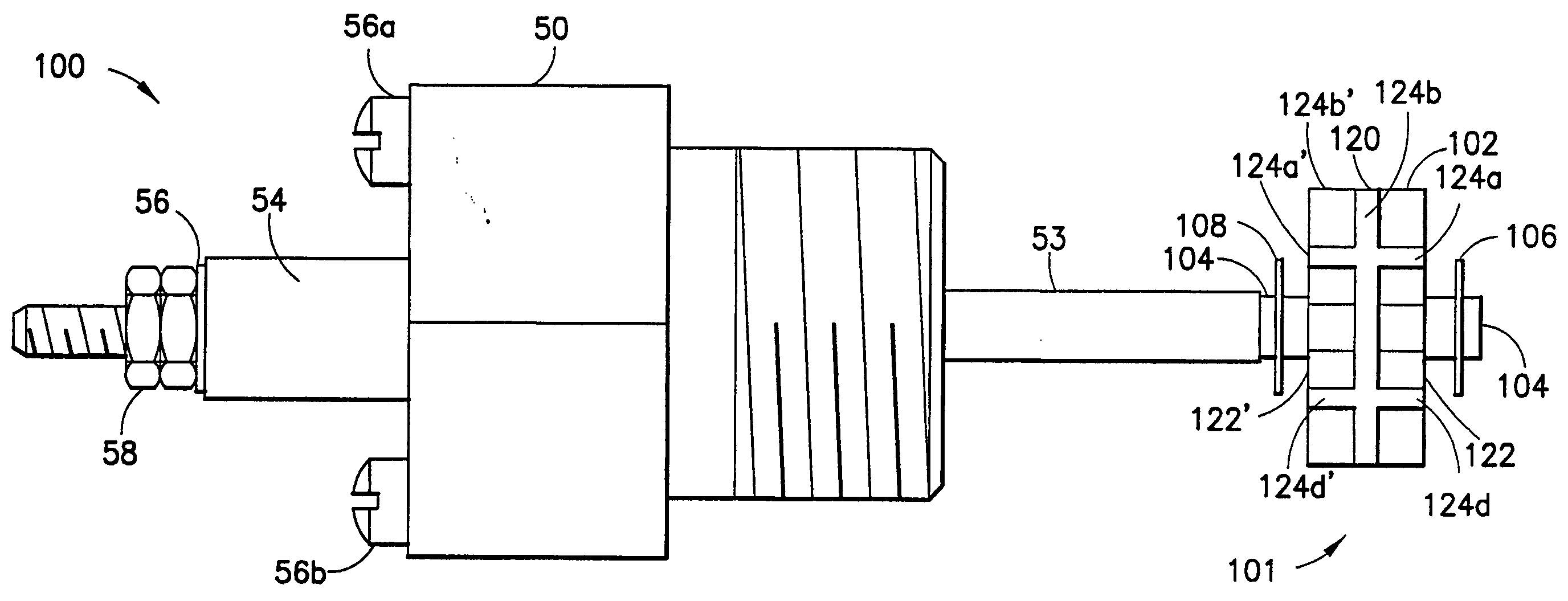
[0037]FIG. 3(a) shows, by way of example, a conductance probe generally indicated as 100 featuring a jiggler arrangement 101 having a jiggler 102 arranged thereon so as to form a mechanical self-cleaning conductance probe according to the present invention. In operation, the jiggler 102 responds to movement of the fluid in a container, such as container element 32 shown in FIG. 1(b), for wiping a surface of a tip 104 of the conductance probe 100 to keep deposits from building up on the same. As shown, the jiggler arrangement 101 includes the jiggler 102 being loosely arranged and retained on the tip 104 by one or more retaining clips 106, 108 arranged thereon so that the jiggler 102 may respond to movement of the fluid, for wiping a surface of the tip 104 to keep deposits from building up on the same.

[0038]FIG. 4(a) shows the tip 104 in the form of an assembly rod having an end generally indicated as 110 with one or more grooves 112, 114 formed therein so that the jiggler 102 (FIG....


PUM


Abstract

A device, having a container for holding a fluid moving therein and a conductance probe installed therein for providing a conductance signal indicating whether it is in contact with the fluid, features a jiggler arrangement having a jiggler arranged on the conductance probe so as to form a mechanical self-cleaning conductance probe, which responds to movement of the fluid, for wiping the conductance probe to keep deposits from building up on the conductance probe. The jiggler arrangement may include one or more grooves thereon so that the jiggler can be loosely fitted on the tip between one or more retaining rings arranged in the one or more grooves. The jiggler arrangement may include one or more retaining rings snap-fit on the tip for loosely arranging and retaining the jiggler on the tip.

Description

BACKGROUND OF THE INVENTION [0001] 1. Field of Invention [0002] The present invention relates to an apparatus for cleaning a probe; and more particularly to an apparatus for continuously cleaning a conductance style probe in a steam or hot water boiler during operation in order to control the water level therein. [0003] 2. Description of Related Art [0004] Conductance style probes are installed in boilers in order to control the water level in the boiler and to prevent the burner from firing if the water level is too low. When water is below the probe, the probe has low conductance and the probe control unit signals the water feeder or pump to turn on and feed water into the boiler. In addition, the burner is prevented from firing because the water level is too low. If the probe is in water, the conductance is high and the probe control unit signals the water feeder or pump to turn off. In addition, the burner is now allowed to fire, if required. In use, as time passes, a layer of d...

Claims


Application Information

Patent Timeline
Patent Type & Authority Applications(United States)
IPC IPC(8): G08B21/00
CPCF24H9/2007G01F23/00G01F23/241G01F23/265G01F23/268Y10T137/8342Y10T137/7306
Inventor BRANZELL, JOHN E.THOMSON, CHRISTOPHER J.
Owner XYLEM IP HLDG
Why Eureka
Try Eureka