Systems and methods for high resolution optical touch position systems

Inactive Publication Date: 2006-06-22
AVAGO TECH ECBU IP (SINGAPORE) PTE LTD
View PDF2 Cites 82 Cited by
  • Summary
  • Abstract
  • Description
  • Claims
  • Application Information

AI Technical Summary

Benefits of technology

[0007] A touch detection system and method is accomplished by surrounding an LCD display with integrated arrays of alternating emitters and detectors. By integrating the arrays into one unit, the size of the detectors can be much greater than that of the emitters and the space between each emitter and its adjacent detector can be reduced to a relatively small amount. In one embodiment, a touch detection system and method is achieved having high resolution by forming an integrated array of alternating emitters and detectors. Using integration techniques, the detectors can be made much larger than the emitters while the gaps between the emitters and detectors are maintained relatively small. Thus, high resolution is achieved without dramatically increasing the number of emitter/detector pairs. In one embodiment each array is positioned on

Problems solved by technology

As a result of the decrease in size of these portable devices, it has become a major technical

Method used


Image

  • Systems and methods for high resolution optical touch position systems
  • Systems and methods for high resolution optical touch position systems
  • Systems and methods for high resolution optical touch position systems

Examples


Embodiment Construction

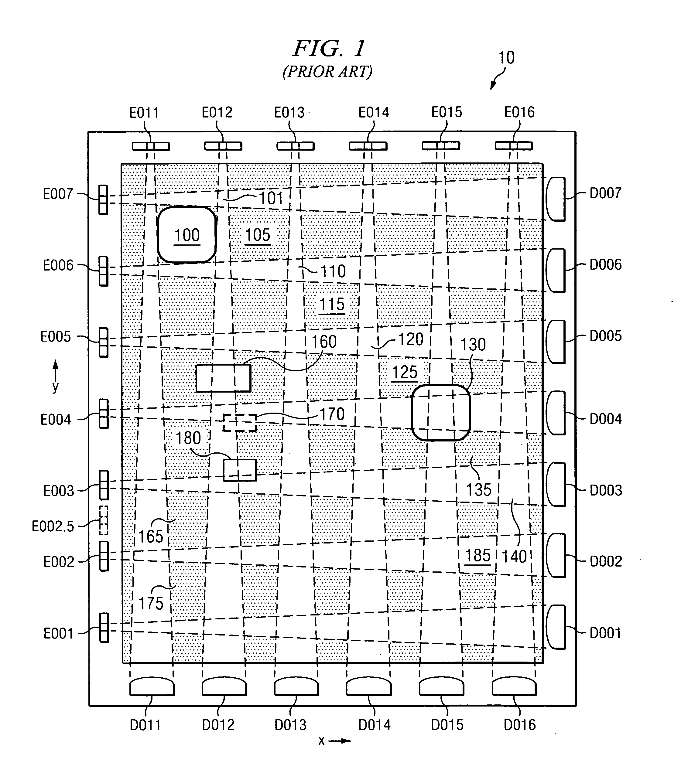
[0015]FIG. 1 depicts one prior art optical touch system. On the vertical axis, emitters are placed on the left side of display 10, while corresponding detectors are placed on the opposite edge of the display, thus forming emitter / detector pairings 001-007 along the vertical (y) axis. Note that each pair (such as pair 001) includes an emitter (such as emitter E001) and a detector (such as detector D001). The same pairings occur on the horizontal axis of display 10, with emitters placed at the top of display 10 and corresponding detectors located at the bottom of the display, forming emitter / detector pairings 011-016 along the horizontal (x) axis. Under the prior art, when contact 130 is sensed, the system scans the y-coordinate by activating emitter / detector pairs 001-007 sequentially. Thus, beginning with emitter / detector pair E001 and D001, the system determines whether the infrared signal between the emitter and corresponding detector has been blocked. This process occurs until th...


PUM


Abstract

In one embodiment, a touch detection system and method is achieved having high resolution by forming an integrated array of alternating emitters and detectors. Using integration techniques, the detectors can be made much larger than the emitters while the gaps between the emitters and detectors are maintained relatively small. Thus, high resolution is achieved without dramatically increasing the number of emitter/detector pairs. In one embodiment each array is positioned on an edge of a display such that the emitter of one array is lined up (on axis with) a detector of an opposing display. In one embodiment, the touch detection system and method operates to detect the amplitude of signals arriving from opposing arrays so as to precisely determine the location of a touched position. Off-axis scanning can be employed to increase sensitivity.

Description

TECHNICAL FIELD [0001] This disclosure is related to optical touch position systems and more particularly to such systems using interleaved emitters and detectors and using full amplitude signal detection and processing. BACKGROUND [0002] Infrared optical touch panels can be found in a variety of systems, most notably on 10″ to 15″ LCD display systems such as ATM terminals, vending machines, and kiosk terminals. By surrounding the LCD with infrared emitters paired with corresponding detectors across the LCD display, the touch panels are able to respond to contact with the screen. Such a response is accomplished by scanning each of the infrared emitters sequentially to determine whether the infrared signal received by the corresponding detector has been “blocked”. When a blocked signal is found, a “touch” is sensed and the position of the touch is calculated based on the “blocked” detector. [0003] For large LCD display systems, such as the ones discussed above, it is easy to place nu...

Claims


Application Information

Patent Timeline
IPC IPC(8): G09G5/00
CPCG01V8/20G06F3/0421
Inventor CHEN, DENG-PENGTAN, WEE-SINLEE, KAI-KOONWONG, CHEE-HENGTAN, SOON-LEEYAMAI, MASATOSHIYEE, PAK-HONGSARAVANAN, RANICHAN, SEOK PENG
Owner AVAGO TECH ECBU IP (SINGAPORE) PTE LTD
Why Eureka
Try Eureka