Retaining device for heat sink

Inactive Publication Date: 2006-06-22
HON HAI PRECISION IND CO LTD +1
View PDF8 Cites 16 Cited by
  • Summary
  • Abstract
  • Description
  • Claims
  • Application Information

AI Technical Summary

Benefits of technology

[0004] Accordingly, an object of the present invention is to provide a heat sink retaining devi

Problems solved by technology

The faster the operation speed is, the larger the amount of heat produced by the electronic device is.
However, excessive heat accumulated at the electronic device is likely to affect operations of the e

Method used


Image

  • Retaining device for heat sink
  • Retaining device for heat sink
  • Retaining device for heat sink

Examples


Embodiment Construction

[0016] Reference will now be made to the drawing figures to describe the present invention in detail.

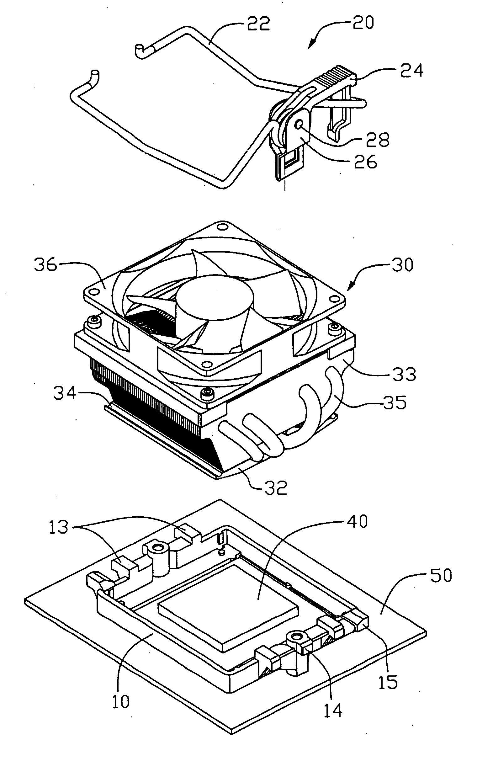
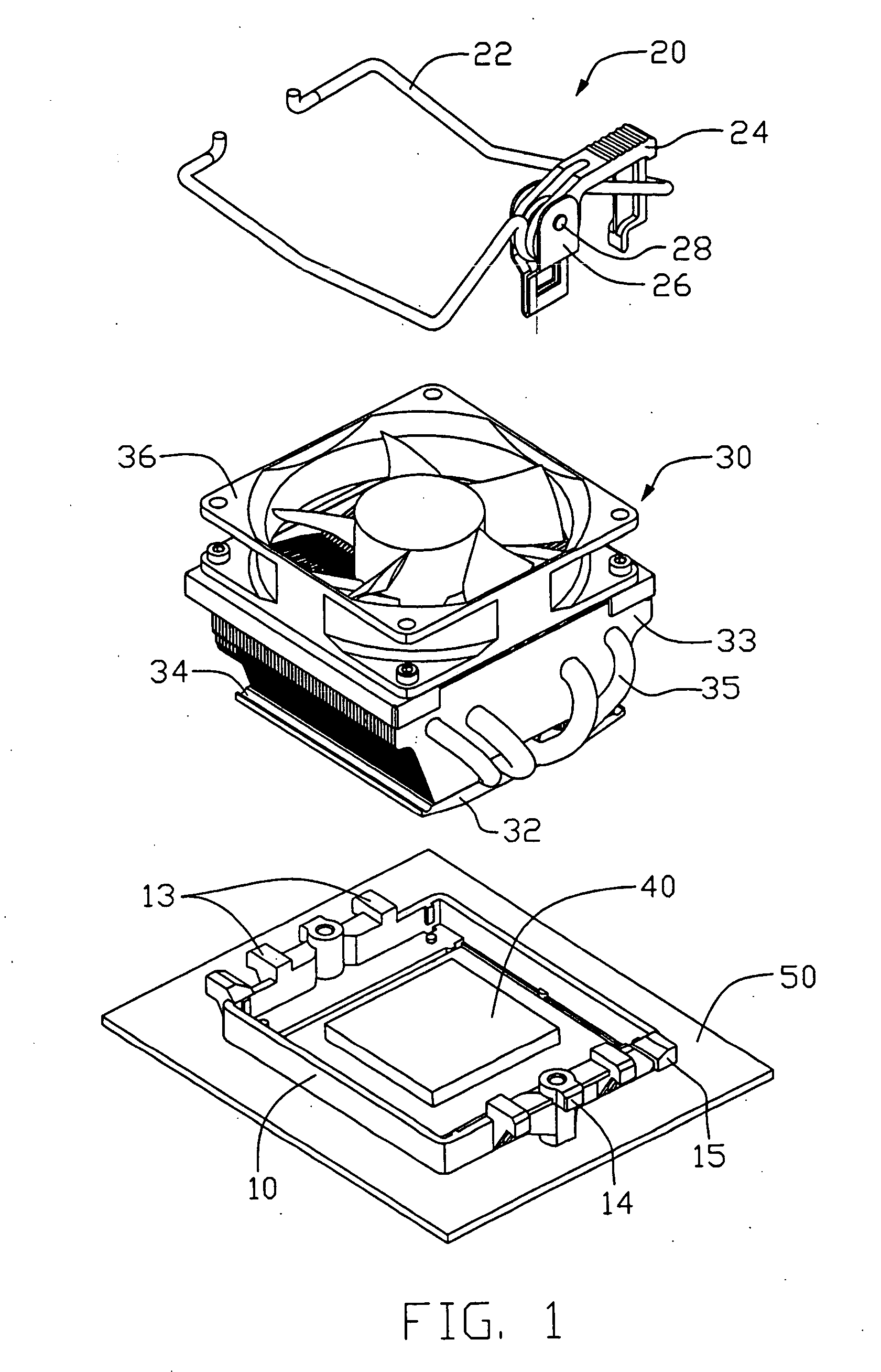
[0017]FIG. 1 illustrates a heat sink retaining device 20 according to a preferred embodiment of the present invention, together with a heat sink 30, an electronic device such as a central processing unit (CPU) 40 mounted on a printed circuit board 50 and a retention module 10 mounted on the printed circuit board 50 surrounding the CPU 40. The retaining device 20 functions to mount the heat sink 30 to the CPU 40 for heat dissipation.

[0018] The retention module 10 has a configuration of rectangular in shape and a plurality of catches 13, 14, 15 formed at opposite sides thereof. The heat sink 30 includes a base 32, a plurality of spaced cooling fins 33 extending upwardly from the base 32 and a cooling fan 36 mounted on a top of the fins 33. A plurality of U-shaped heat pipes 35 connects the base 32 with an upper portion of the fins 33. The base 32 defines at opposite sides thereof a p...


PUM


Abstract

A retaining device (20) for mounting a heat sink (30) to an electronic device (40) includes an unitary metal wire clip (22), a locking device (26) and a camming member (24). The clip includes a pair of spaced apart pressing beams (221), at least one latching beam (223) and a crossbeam (225). The latching beam is set at one side of the pressing beams. The crossbeam extends between the pressing beams at an opposite side thereof. The camming member is pivotably attached to the locking device and includes a cam (242) being engageable with the crossbeam. The camming member is pivotable relative to the locking device from an unlocked position to a locked position and the pressing beams force the heat sink into close contact with the electronic device when the camming member is located at the locked position.

Description

TECHNICAL FIELD [0001] The present invention relates generally to a reining device for heat sink, and more particularly to a retaining device which can conveniently mount a heat sink to an electronic device. BACKGROUND [0002] It is widely acknowledged that heat is produced during operations of electronic devices such as clipsets or processors of computers. The faster the operation speed is, the larger the amount of heat produced by the electronic device is. However, excessive heat accumulated at the electronic device is likely to affect operations of the electronic device and even results in computer crashes. Therefore, a heat dissipation device such as a heat sink is needed for heat dissipation of the electronic device. [0003] In order to keep the heat sink into close contact with the electronic device, retaining devices such as retainers or fasteners are generally required. FIGS. 7-8 illustrate a prior art heat sink retainer 20 used for attaching a heat sink 40 to a central proces...

Claims


Application Information

Patent Timeline
IPC IPC(8): H05K7/20
CPCH01L23/4093H01L23/427H01L23/467Y10T24/44026H01L2924/0002H01L2924/00
Inventor YU, FANG-XIANGLEE, MENG-TZULIN, SHU-HOCAO, MING-KUN
Owner HON HAI PRECISION IND CO LTD
Why Eureka
Try Eureka