
Fuel cell in which a fluid circulates essentially parallel to the electrolytic membrane and method for production of such a fuel cell

Inactive Publication Date: 2006-06-22
COMMISSARIAT A LENERGIE ATOMIQUE ET AUX ENERGIES ALTERNATIVES
View PDF10 Cites 5 Cited by
  • Summary
  • Abstract
  • Description
  • Claims
  • Application Information

AI Technical Summary

Benefits of technology

[0008] It is an object of the invention to remedy these shortcomings and more particularly to propose a fuel cell enabling both efficient and quick removal of the compounds formed when operating and enabling the reactive fluids to be quickly renewed.
[0013] It is a further object of the invention to provide a method for production of such a fuel cell that is easy to implement and using techniques implemented in the microtechnology field.

Problems solved by technology

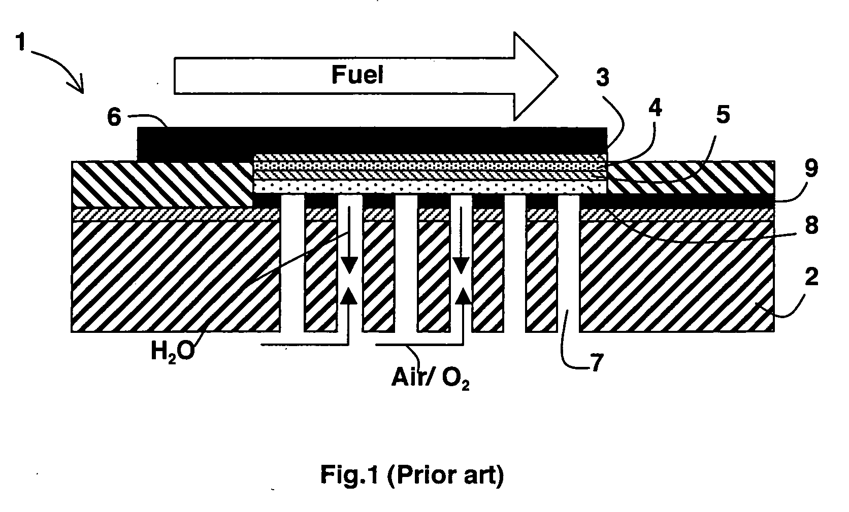
In fuel cells, providing the electrodes with reactive fluid and removing the products formed when the cell operates represent two major difficulties, in particular in micro fuel cells used in portable equipment.
This type of reactive fluid supply is however not satisfactory.

Method used


Image

  • Fuel cell in which a fluid circulates essentially parallel to the electrolytic membrane and method for production of such a fuel cell
  • Fuel cell in which a fluid circulates essentially parallel to the electrolytic membrane and method for production of such a fuel cell
  • Fuel cell in which a fluid circulates essentially parallel to the electrolytic membrane and method for production of such a fuel cell

Examples


Embodiment Construction

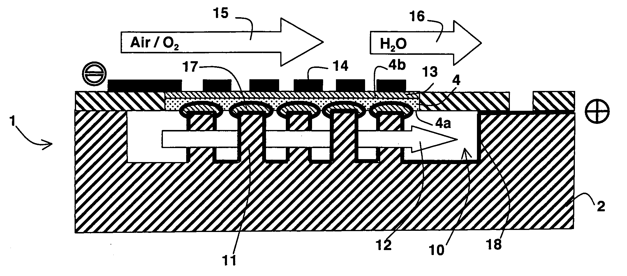
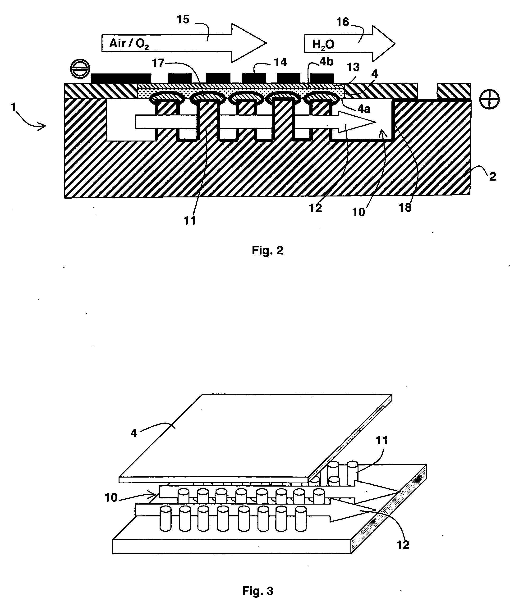
[0025] A fuel cell according to the invention comprises a substrate supporting an electrolytic membrane comprising first and second faces. First and second electrodes are respectively arranged on the first and second faces of the electrolytic membrane and they respectively comprise first and second catalytic elements designed to trigger an electrochemical reaction. First and second fluids are respectively designed to be brought near to the first and second catalytic elements. Supply of the first fluid is thus performed in such a way as to make the latter flow substantially parallel to the first face of the electrolytic membrane in a cavity formed in the substrate, and to bring it into contact with the first catalytic element. The first fluid associated with the first catalytic element can thus be either the combustive-fuel associated with the catalytic element of the cathode or the fuel associated with the catalytic element of the anode. The cavity formed in the substrate can compri...


PUM

PropertyMeasurementUnit
Distanceaaaaaaaaaa
Flow rateaaaaaaaaaa

Abstract

The invention relates to a fuel cell, comprising a substrate supporting an electrolytic membrane with first and second faces on which first and second electrodes are respectively arranged. The first and second electrodes respectively comprise first and second catalytic elements and first and second fluids are respectively provided for supply to the neighbourhood of the first and second catalytic elements. The supply of the first fluid on the neighbourhood of the first catalytic element is embodied such as to generate a circulation essentially parallel to the first face of the electrolytic membrane, in a cavity formed in the substrate.

Description

BACKGROUND OF THE INVENTION [0001] The invention relates to a fuel cell, and more particularly a micro fuel cell, comprising a substrate supporting an electrolytic membrane comprising first and second faces on which first and second electrodes are respectively arranged, the first and second electrodes respectively comprising first and second catalytic elements, circulation means being designed to bring first and second fluids respectively in proximity to the first and second catalytic elements. [0002] The invention also relates to a method for production of such a fuel cell. STATE OF THE ART [0003] In fuel cells, providing the electrodes with reactive fluid and removing the products formed when the cell operates represent two major difficulties, in particular in micro fuel cells used in portable equipment. Miniaturization of fuel cells does in fact impose storage and a circulation circuit for the fuel, the combustive-fuel and the products formed in the course of operation of the cel...

Claims


Application Information

Patent Timeline
IPC IPC(8): H01M8/02H01M8/10B05D5/12C03C25/68H01M4/86H01M4/88H01M8/04
CPCH01M4/8626H01M8/04089H01M8/1004H01M8/1097H01M2008/1095Y02E60/521Y02P70/56
Inventor LAURENT, JEAN-YVES
Owner COMMISSARIAT A LENERGIE ATOMIQUE ET AUX ENERGIES ALTERNATIVES
Learn More