Prestressed composite girder, continuous prestressed composite girder structure and methods of fabricating and connecting the same

a technology of prestressed composite girders and steel plates, which is applied in the direction of girders, bridges, joists, etc., can solve the problems of low rigidity, crude appearance, and greater clearance of girders, so as to reduce the clearance of girders, compact and economical construction, and increase rigidity

Inactive Publication Date: 2006-06-29
KOO MIN SE
View PDF8 Cites 22 Cited by
  • Summary
  • Abstract
  • Description
  • Claims
  • Application Information

AI Technical Summary

Benefits of technology

[0007] Accordingly, it is an object of the present invention to provide a prestressed composite girder, a continuous prestressed composite girder structure and methods of fabricating and connecting the same, in which steel plates are embedded in the upper and lower flanges of the prestressed composite girder, so that the rigidity thereof is increased, thus reducing the clearance thereof and, thus, achieving a compact and economical construction.

Problems solved by technology

However, the conventional prestressed composite girder is formed of only concrete, so that the rigidity thereof is low compared to a steel structure formed of a steel and, thus, the clearance thereof must be greater.
Accordingly, the conventional prestressed composite girder is disadvantageous in that the appearance thereof looks crude and it can not be applied to the a bridge across river, which requires a sufficient overhead clearance.
Furthermore, the horizontal reinforcing bars functioning to combine an upper floor slab with the conventional prestressed composite girder must be removed from a completed structure, so that the conventional prestressed composite girder is uneconomical in that reinforcing bars more that those required for the conventional prestressed composite girder itself are arranged in the conventional prestressed composite girder.

Method used


Image

  • Prestressed composite girder, continuous prestressed composite girder structure and methods of fabricating and connecting the same
  • Prestressed composite girder, continuous prestressed composite girder structure and methods of fabricating and connecting the same
  • Prestressed composite girder, continuous prestressed composite girder structure and methods of fabricating and connecting the same

Examples


Embodiment Construction

[0019] Reference will now be made in detail to the present preferred embodiments of the present invention, examples of which are illustrated in the accompanying drawings, wherein like reference numerals refer to like elements throughout.

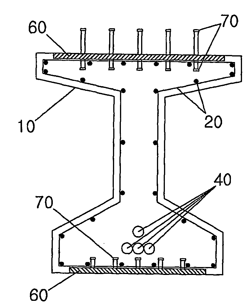
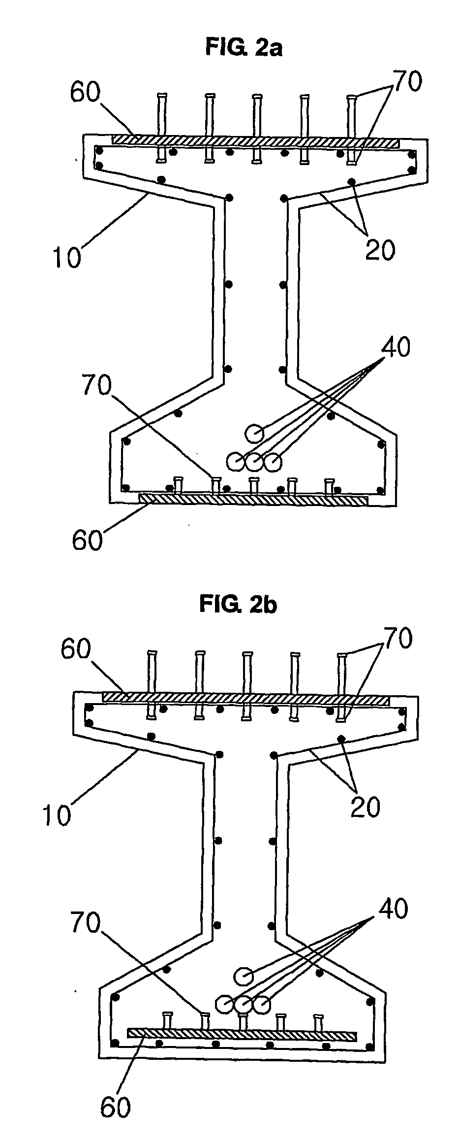
[0020]FIGS. 2A to 7 are views showing a prestressed composite girder including steel plates. FIGS. 2A and 2B are views showing the front cross-sections of a composite girder with steel plates according the present invention. FIGS. 3A to 3C are a moment diagram and side cross-sections of the composite girder with steel plates according the present invention in the case of a simple bridge, respectively. FIGS. 4A to 4D are a moment diagram and side cross-sections of the composite girder with steel plates according the present invention in the case of an outside span of a continuous bridge, respectively. FIGS. 5A to 5D are a moment diagram and side cross-sections of the composite girder with steel plates according the present invention in the case of an...


PUM


Abstract

Disclosed herein are a prestressed composite girder with steel plates, a continuous prestressed composite girder structure with steel plates and methods of fabricating and connecting the same. The prestressed composite girder includes shear reinforcing bars and main reinforcing bars, sheaths, sole plates, and steel plates. The shear reinforcing bars and main reinforcing bars are arranged across the prestressed composite girder. The sheaths are adapted to contain steel wires arranged across the prestressed composite girder. The sole plates are placed at ends of the prestressed composite girder and provided with shear connecting members. The steel plates are placed in upper and lower flanges of the prestressed composite girder and provided with shear connecting members.

Description

TECHNICAL FIELD [0001] The present invention relates to a prestressed composite girder with steel plates, a continuous prestressed composite girder structure with steel plates and methods of fabricating and connecting the same. BACKGROUND ART [0002] For prior art, there are a prestressed composite girder formed of concrete without steel plates, and a continuous prestressed composite girder structure formed by simply using bolts. [0003]FIGS. 1A and 1B are front and side sectional views showing a conventional prestressed composite girder 10 that is widely used. [0004]FIG. 1A is a front sectional view of the conventional prestressed composite girder 10. Referring to FIG. 1A, a concrete structure 10 includes shear reinforcing bars and main reinforcing bars 20, horizontal shear reinforcing bars 30 combining an upper floor slab with the conventional prestressed composite girder, and sheaths 40 including steel wires to introduce a compressive force to the lower end of the tensile side of t...

Claims


Application Information

Patent Timeline
Patent Type & Authority Applications(United States)
IPC IPC(8): E01D2/00E04C3/292
CPCE01D2/02E01D2101/285E04C3/26E04C3/292E04C3/293E04C5/0645
Inventor PARK, YOUNG JE
Owner KOO MIN SE
Why Eureka
Try Eureka