Stackable container and container blank (L corner)
Inactive Publication Date: 2006-06-29
WEYERHAEUSER CO
9 Cites 10 Cited by
AI-Extracted Technical Summary
Problems solved by technology
The result is a reduction of structural integrity, and may include crushing or other damage to the container contents.
In addition, when the walls of one or more containers in a stack are crushed, wholly or partly collapsed, or otherwise deformed, the deformed container may no longer provide a stable horizontal support for containers stacked over it.
A leaning “tower” of containers may fall, and even if there is no injury to persons, the contents of the containers may spill or be damaged.
Apart from instability due to parti...
Abstract
A tray-type container includes a bottom wall, longitudinally-extending outer side walls, and laterally-extending end walls, the outer side walls and the end walls extending upwardly from the bottom wall to form an inner cavity. A plurality of tray-type containers may be unitized in several stacked configurations. Typically, the plurality of unitized containers are placed upon a shipping pallet or slip sheet, or placed within a shipping container to facilitate shipping by large carriers.
Application Domain
Rigid containers
Technology Topic
Shipping containerSlip sheet +1
Image
Examples
- Experimental program(1)
Example
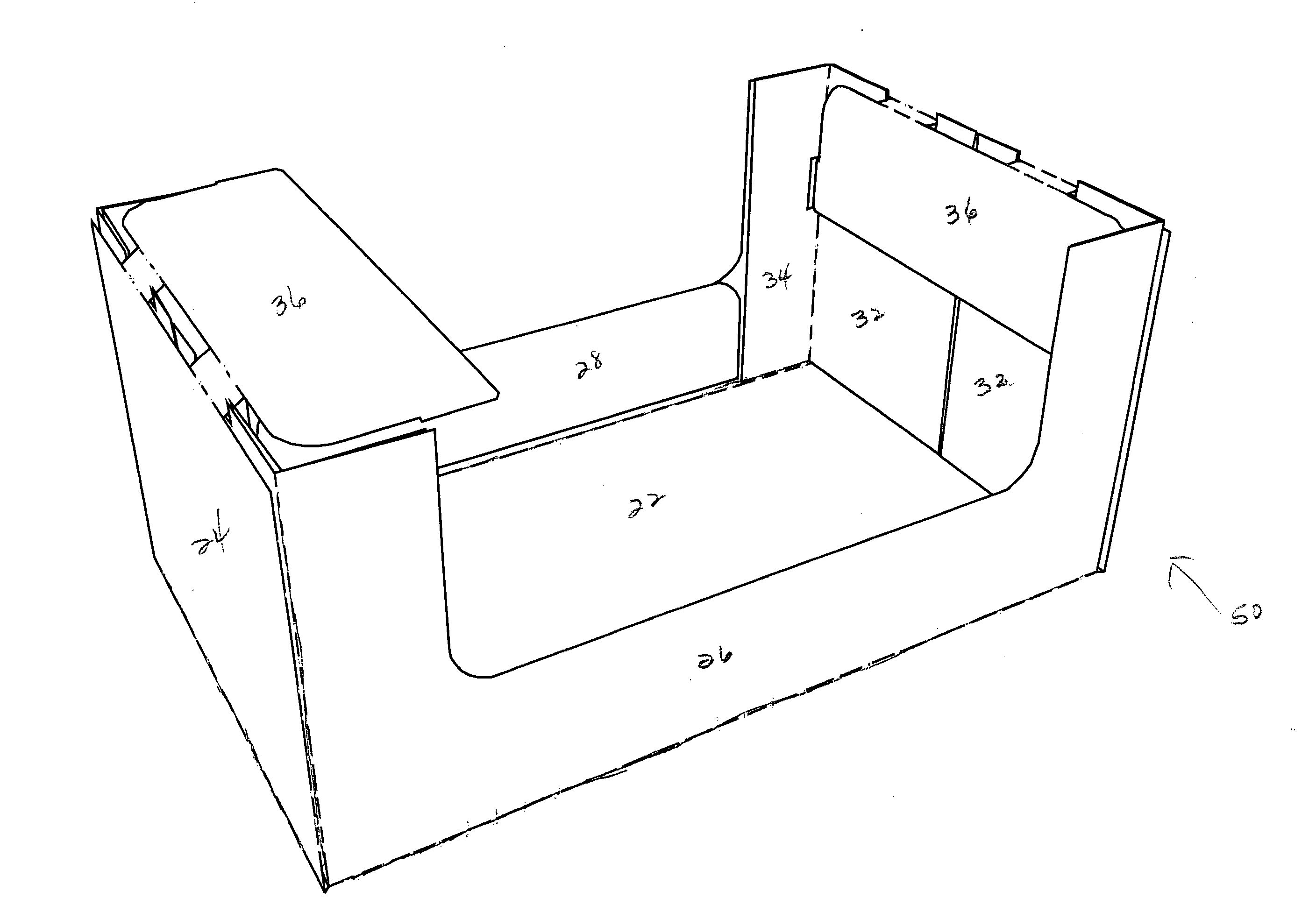
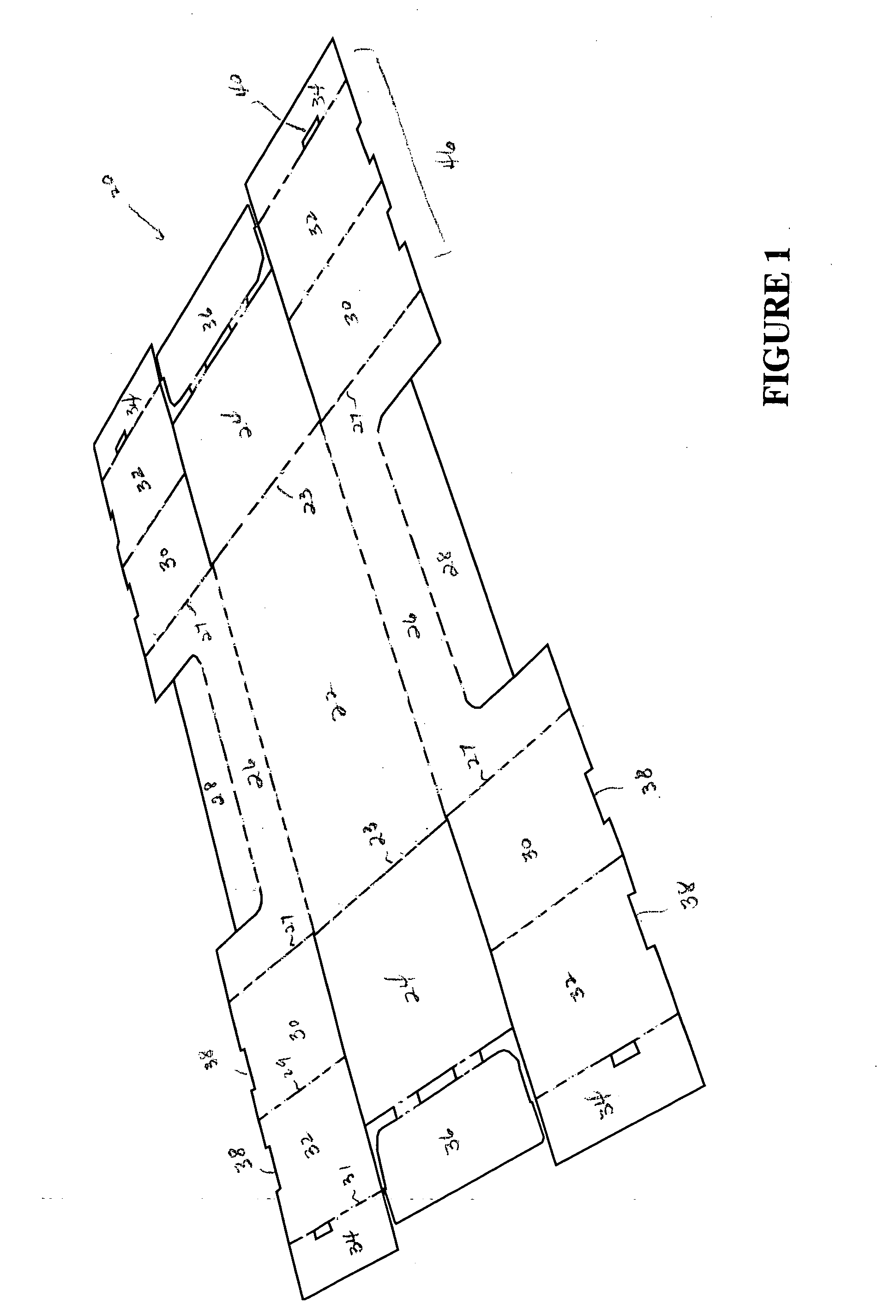
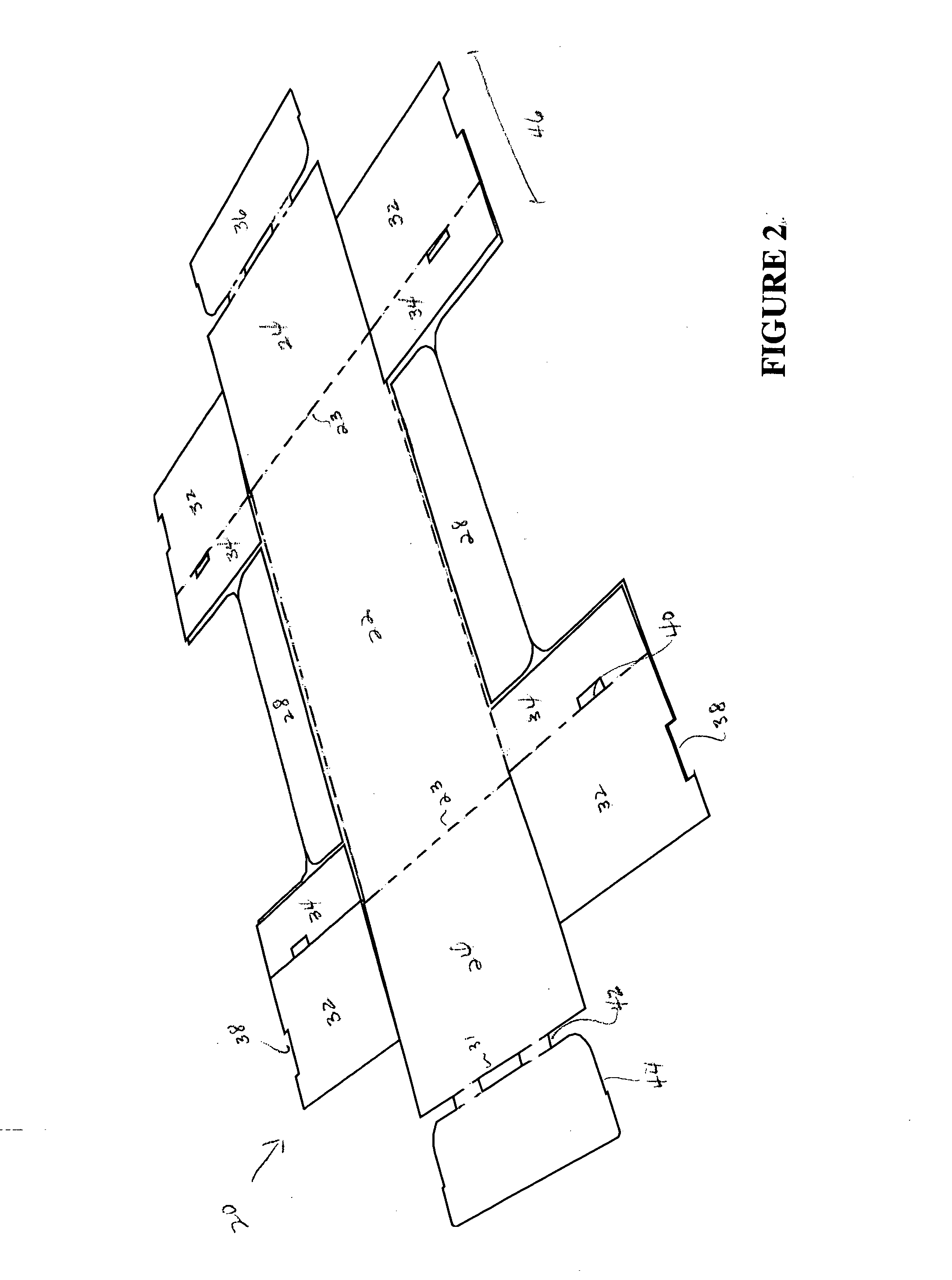
[0014] The present invention includes a single sheet of foldable material cut and scored to form a blank formable into a container. By way of overview and with reference to FIGS. 1-5, an embodiment of the present invention includes a single piece blank 10 arranged to form a stackable container 50. Specific details of the blank 20 and container 50 are described with more particularity below.
[0015] The present invention will now be described with reference to the accompanying FIGS. 1-5 where like numerals correspond to like elements. In all FIGURES, cut lines are shown as solid lines, score lines or lines of weakness are shown as broken lines. The present invention is directed to a tray-type container that utilizes a corner assembly to create a modular stackable container. The container includes an arrangement of panels, which are adapted to provide suitable container stability.
[0016] One suitable embodiment of the blank 20, constructed in accordance with the present invention is illustrated in FIGS. 1 and 5. The blank 20 and container 50 include a bottom panel 20, longitudinally-extending outer side walls 26, and laterally-extending end walls 24. A plurality of tray-type containers 10 may be placed upon a shipping pallet or slip sheet (not shown), or placed within a shipping container (not shown) to facilitate shipping or displaying at a retail location.
[0017] For the purpose of further description herein, the downward direction is defined as the direction perpendicular to bottom panel 22 that corresponds to the outer surface of the bottom panel when the container has been erected, and the upward direction is defined as the direction perpendicular to the bottom panel that corresponds to the inner surface of the bottom panel when the container has been erected.
[0018] The blank 20 and resulting container 50 is typically made from any suitable material used in the shipping, storing or displaying of goods. Suitable, nonlimiting examples of such materials include paperboard, containerboard, cardboard, pasteboard, fiberboard, corrugated containerboard, corrugated paperboard, single wall corrugated containerboard, multiwall corrugated containerboard or a combination thereof. As best shown in FIG. 1, a blank 20 is stamped out of any of these suitable materials and assembled in a manner which can be seen in FIGS. 1-5.
[0019] With continued reference to FIG. 1, the blank 20 includes a bottom panel 22 of generally rectangular shape having multiple edges. It will be appreciated, however, that the bottom panel 22 may also be of other geometries, such as, without limitation, square. Unless otherwise apparent, the term “edges” refers generally to a zone or line of weakness along which a part can be folded, such as a score line, or a cut line. Opposite outer side wall panels 26 are hingedly connected to opposite side edges of the bottom panel 22 along fold lines 21. The blank 20 further includes end panels 24, which are hingedly connected to the remaining two opposite edges of the bottom panel 22 along fold lines 23. The outer side panels 26 include inner side panels 28, which are hingedly connected to the outer side panels 26, along a fold line 33, opposite the bottom panel 22.
[0020] Further, the outer side panels 26 include corner assemblies 46 located at opposite ends of outer side wall panels 26, and are hingedly connected to the outer side panels 26 along fold lines 27. The fold lines 27 are substantially perpendicular to fold lines 21. The corner assemblies 46 include a first corner panel 30 connected with the outer side panel 26 along fold line 27. A second corner panel 32 is connected with the first corner panel 30 along fold line 29, opposite fold line 27. A third corner panel 34 is connected with the second corner panel 32 along fold line 31, opposite fold line 29. The first corner panel 30 and the second corner panel 32 each include a hinge flap notch 38. The hinge flap notch 38 is typically formed in an edge that lies substantially perpendicular to fold lines 27, 29, and 31. Additionally, the third corner panel 34 includes a locking tab slot 44. The locking tab slot 44 is generally formed in the third corner panel 34, adjacent or along fold line 31.
[0021] The end panels 24 include end panel flaps 36, which are hingedly attached to the end panel 24, opposite the bottom panel 22, by hinge flaps 42 along interrupted cut line 31. As depicted in the FIGURES, only two hinge flaps 42 are used, however, it will be appreciated that the present invention may include more or fewer hinge flaps 42 without exceeding the spirit and scope of the present invention. Positioned on an outer edge of the end panel flaps 36 are locking tabs 40. Those skilled in that art will appreciate that the locking tabs 40 and the locking tab slot 44 are configured to interact upon formation of the container 50 (discussed in more detail below), to lock the container 50 in its assembled form. dead
[0022] Referring now to FIGS. 2-5, one method of constructing the container 50 from the blank 20 will be described. In the ensuing description, erecting one side of the containers will be described. However, it will be appreciated that the other side of the container is formed in substantially similar steps. The first step begins with the inner side panel 28 being folded inwardly, about fold line 33, approximately 180° such that the inner side panel 28 and the outer side panel 26 lie adjacent one another and in parallel planes. Additionally, both the second corner panel 32 and the third corner panel 34 are folded inwardly, about fold line 29, approximately 180° such that the second corner panel 32 and the third corner panel 34 lie adjacent the first corner panel 30 and a portion of the outer side wall 26. FIG. 2, best represents the container at this stage of formation.
[0023] With specific reference to FIGS. 3 and 4, additional stages of container formation are depicted. Specifically, the first corner panel 30 and the second corner panel 32 are folded upwardly approximately 90°, about fold lines 27 and 31, respectively. In this manner, the first corner panel 30 and the second corner panel 32 lie adjacent one another and lie in a plane that is substantially perpendicular to the third corner panel 34 and outer side wall 26. Then the entire wall panel and corner assembly 46 is folded upwardly along fold line 21 such that the first corner panel 30 and the second corner panel 32 lie in a plane parallel to fold line 23.
[0024] Further, end panels 24 are then folded upright, along fold line 23, approximately 90° with respect to the bottom wall panel 22, as best shown in FIG. 4. In this position, the hinge flap notches 38 are along an upper edge of the end walls of the container 50 are spatially positioned to receive hinge flaps 42 when the end panel flap 36 if folded over the first corner panel 30 and the second corner panel 32 as depicted in FIG. 5. The locking tabs 44 may then be inserted into the locking tab slots 40 to help hold the container 50 in an erect position.
[0025] In use, container 50 may be filled with product (not shown) and stacked with one or more other containers 50 on a pallet (not shown) or display shelf (not shown). In one possible application, a selected number of containers 50 filled with product (not shown) are stacked on pallet (not shown), and pallet (not shown) may be moved from receiving directly to the display floor of the retailer (perhaps after removing an external common cover, strapping or wrap), where end-user purchasers have access to the pallet of containers. The individual containers 50 may not include covers, tops or lids of corrugated material, instead being arranged such that the upper containers engage over and cover the next lower one. The containers 50 are accessed on the display floor and generate less waste. Purchasers may select product (not shown) from one of the open containers 50, generally from those containers at the top of the stack. The increased strength of the containers allows the containers to better resist vertical collapse or lateral deflection caused by the forces of handling and the like. Handholds (not shown) allow containers to be easily manipulated by stock personnel or others, individually or in stacks of two or more.
[0026] As another alternative, the container of the invention may also include a top or other means to cover the container. In addition to the advantages apparent from the foregoing description, the present invention improves the container's strength, especially crushed in the vertical direction. A related advantage is that the contents of such containers are less likely to be damaged.
[0027] While an embodiment of the invention has been illustrated and described, as noted above, many changes can be made without departing from the spirit and scope of the invention. For example, the blank may also include other features specified by the customer, such as hand holds, vent holes, grease or moisture barriers and the like without exceeding the scope of the present invention. Accordingly, the scope of the invention is not limited by the disclosure of the preferred embodiment. Instead, the invention should be determined entirely by reference to the claims that follow.
PUM


Description & Claims & Application Information
We can also present the details of the Description, Claims and Application information to help users get a comprehensive understanding of the technical details of the patent, such as background art, summary of invention, brief description of drawings, description of embodiments, and other original content. On the other hand, users can also determine the specific scope of protection of the technology through the list of claims; as well as understand the changes in the life cycle of the technology with the presentation of the patent timeline. Login to view more.