Connection terminal and connector equipped therewith

Active Publication Date: 2006-06-29
JST MFG CO LTD
View PDF5 Cites 3 Cited by
  • Summary
  • Abstract
  • Description
  • Claims
  • Application Information

AI Technical Summary

Benefits of technology

[0005] However, in these connectors disclosed in the above documents, since connection terminals are placed on a substrate, the connectors are made greater in height when actua

Problems solved by technology

Further, the manufacturing cost is increased because of attaching by press-fitting connection terminals into through holes formed on the substrate.
However, in an environment which produces vibration, heat, etc., they cannot

Method used


Image

  • Connection terminal and connector equipped therewith
  • Connection terminal and connector equipped therewith
  • Connection terminal and connector equipped therewith

Examples


Example

Embodiment 1

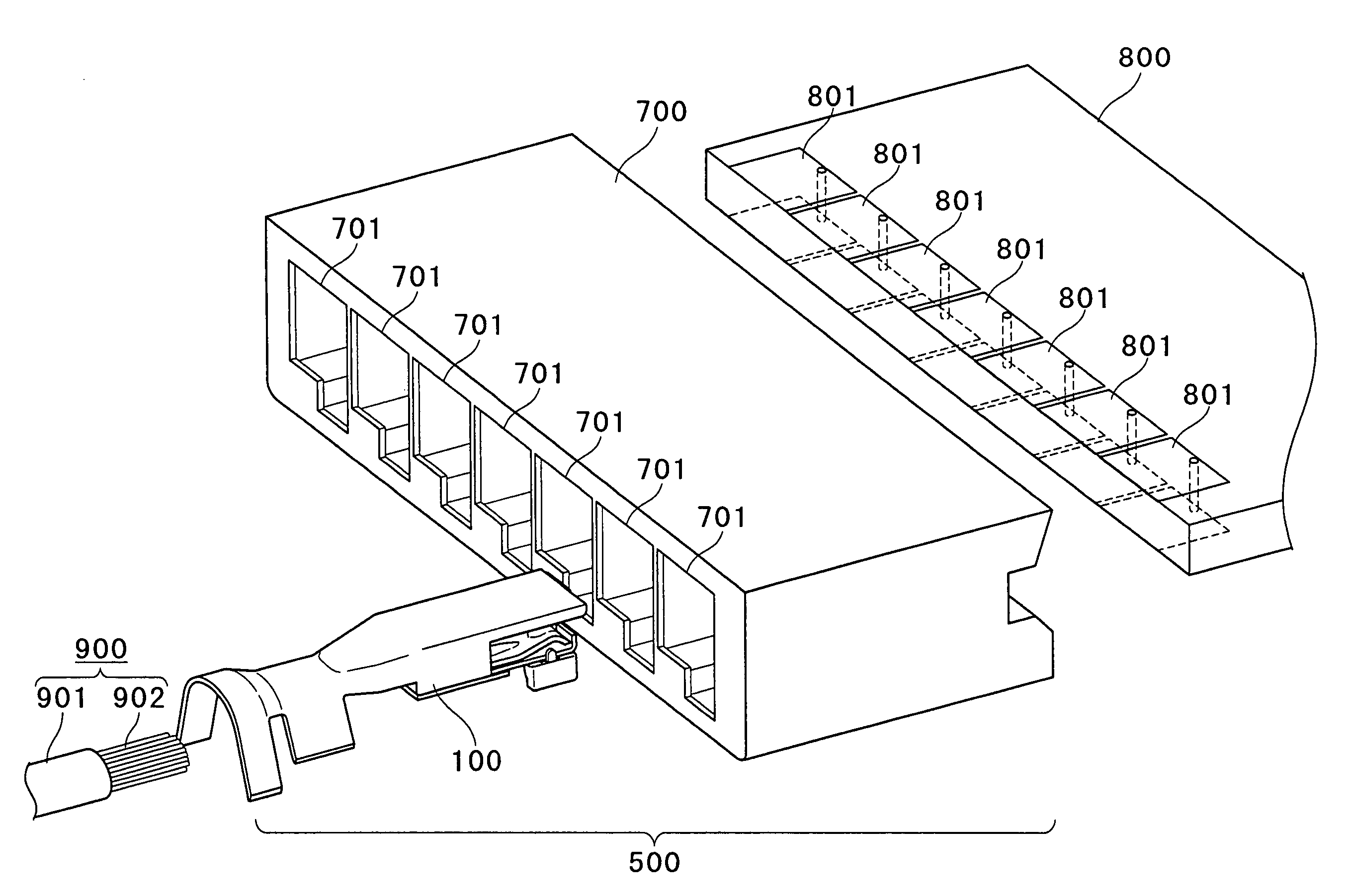
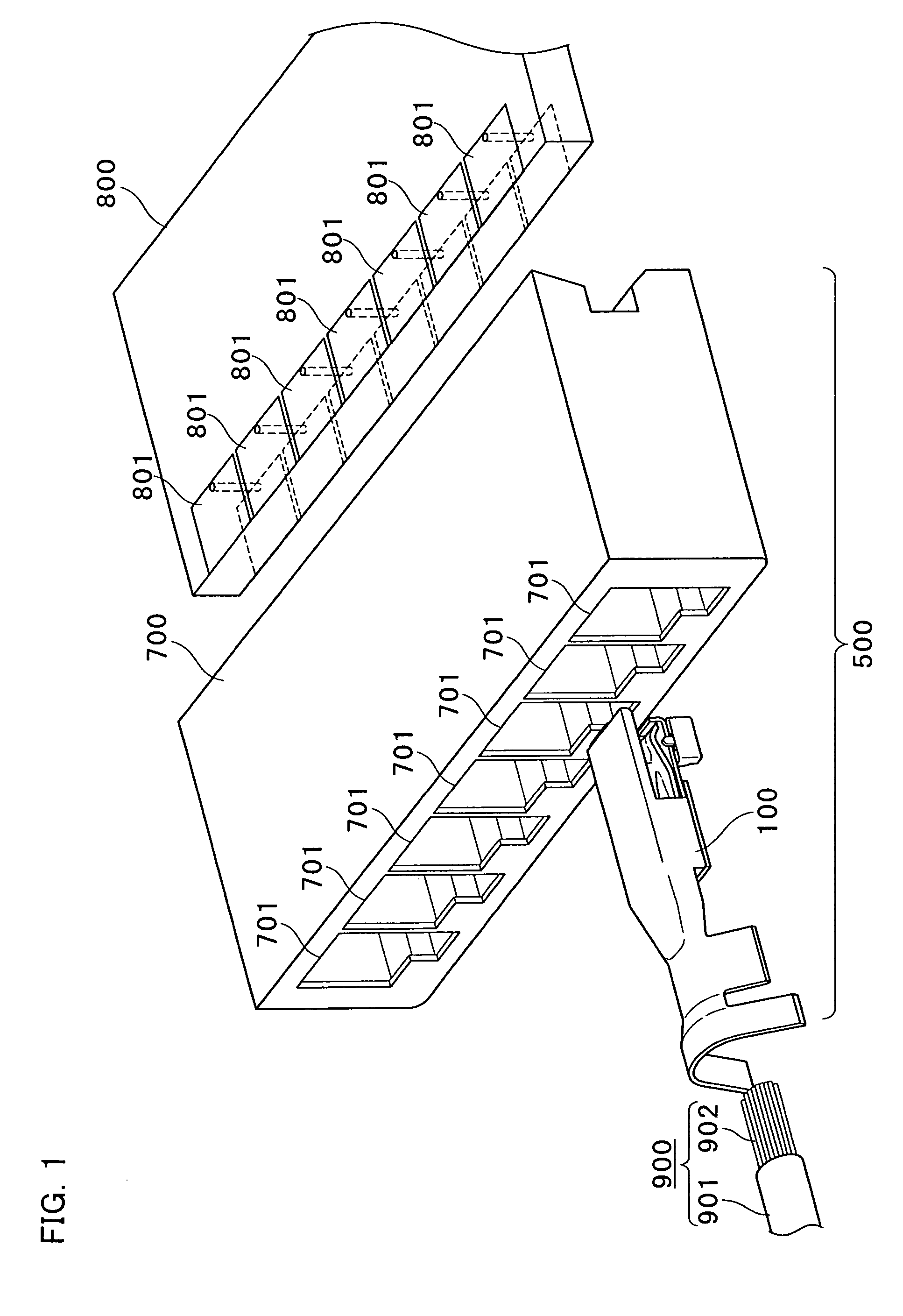
[0052]FIG. 1 is an assembly drawing showing appearances of a card edge connector 500, a substrate 800 and a cable 900 of the embodiment 1 of the present invention.

[0053] As shown in FIG. 1, the card edge connector 500 includes a housing 700 and a card edge terminal 100. The housing 700 is provided with a plurality of through holes 701.

[0054] Further, although a single card edge terminal 100 is shown in FIG. 1, it is shown, with other card edge terminals 100 omitted, for a simplified explanation. A plurality of card edge terminals 100 is actually inserted in the number corresponding to a plurality of through holes 701 of the housing 700.

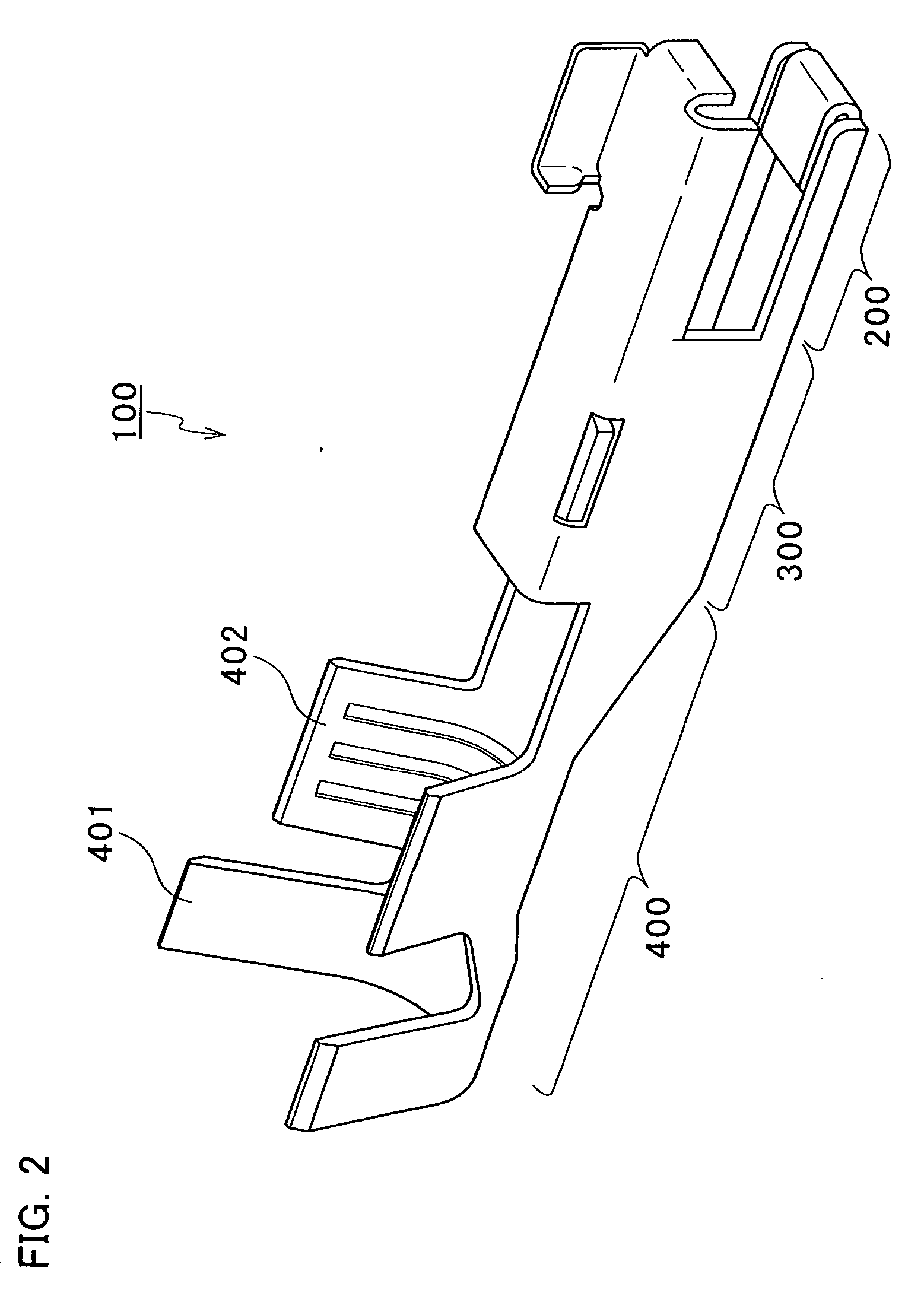
[0055] The card edge terminal 100 is electrically connected to the cable 900. A conductor 902 from which a coated part 901 of the cable 900 is removed is provided at an edge of the cable 900. As will be explained later, the coated part 901 of the cable 900 and the conductor 902 are attached by crimping by the crimping part 400 of the c...


PUM


Abstract

The card edge connector includes a housing and a card edge terminal. A plurality of through holes is formed on the housing. A cable is electrically connected to the card edge terminal. The card edge terminal to which the cable is attached by crimping is pressed and inserted into a plurality of through holes on the housing. Conductor areas are provided on the surface and the back of the substrate. The substrate is inserted and fitted into the housing and also held by the holding part of the card edge terminal which is pressed and inserted into the housing and electrically conducted to the conductor areas.

Description

TECHNICAL FIELD [0001] The present invention relates to a connection terminal which can electrically connect an electric wiring with conductor areas of a substrate and also relates to a connector equipped therewith. BACKGROUND ART [0002] There have been so far developed various types of connectors capable of providing an electrical connection depending on use status. A tuning-fork type contact, a bellows type contact, a cantilever-type contact and others have been used inside these connectors as a connection terminal for providing an electrical connection. [0003] For example, in some connectors for connecting a cable with a substrate, one end of a tuning-fork type contact is used to hold the cable and the other end of the tuning-fork type contact is inserted into a through hole of the substrate, thereby making it possible to electrically connect the cable with the substrate. [0004] Japanese Published Unexamined Patent Application No. H11-185898 has disclosed a right angle connector ...

Claims


Application Information

Patent Timeline
IPC IPC(8): H01L23/48
CPCH01R13/113H01R12/721
Inventor NAGAMINE, AKIRACHIYODA, MEGUMI
Owner JST MFG CO LTD
Why Eureka
Try Eureka