Distributed aperture head-up display

a head-up display and distribution aperture technology, applied in the field of displays, can solve the problems of decreased aperture ratio, undesirable and distracting visual artifacts, inherent structural periodicity, etc., and achieve the effects of reducing spatial harmonics and associated artifacts, reducing visual artifacts, and reducing higher harmonics

Active Publication Date: 2006-06-29
HONEYWELL INT INC
View PDF16 Cites 29 Cited by
  • Summary
  • Abstract
  • Description
  • Claims
  • Application Information

AI Technical Summary

Benefits of technology

[0008] An apparatus is provided for displaying an image to a viewer with reduced visual artifacts. The apparatus comprises a display panel for forming the image using an array of pixels with distributed active regions, and a viewing arrangement optically situated between the display panel and the viewer for transferring the image formed on the display panel to the viewer with limited angular pixel subtense. The distributed active regions of the pixels are desirably divided into at least two simultaneously switched portions at least partly separated by or surrounding a significant portion of the non-switchable region. First order spatial harmonics and associated artifacts are reduced by the distributed apertures and second order and higher harmonics are reduced by limiting the pixel subtense angle seen by the viewer. A significant reduction in visual artifacts arising from the periodic structure of the display panel is obtained.

Problems solved by technology

The above-described inherent structural periodicity is a significant limitation of pixeled displays since it can create undesirable and distracting visual artifacts in the display output that have nothing to do with the information desired to be presented.
While these may be helpful in ameliorating some of the inherent artifacts, they have undesirable side effects such as for example, decreased aperture ratio, decreased display efficiency, increased complexity and cost and, sometimes, other visual artifacts (e.g., a speckled appearance).

Method used


Image

  • Distributed aperture head-up display
  • Distributed aperture head-up display
  • Distributed aperture head-up display

Examples


Embodiment Construction

[0021] The following detailed description is merely exemplary in nature and is not intended to limit the invention or the application and uses of the invention. Furthermore, there is no intention to be bound by any expressed or implied theory presented in the preceding technical field, background, brief summary or the following detailed description. As used herein, the terms “ON” and “OFF” with respect to switchable pixel elements or regions are intended to include any analog level change in properties and not be limited merely to binary switching.

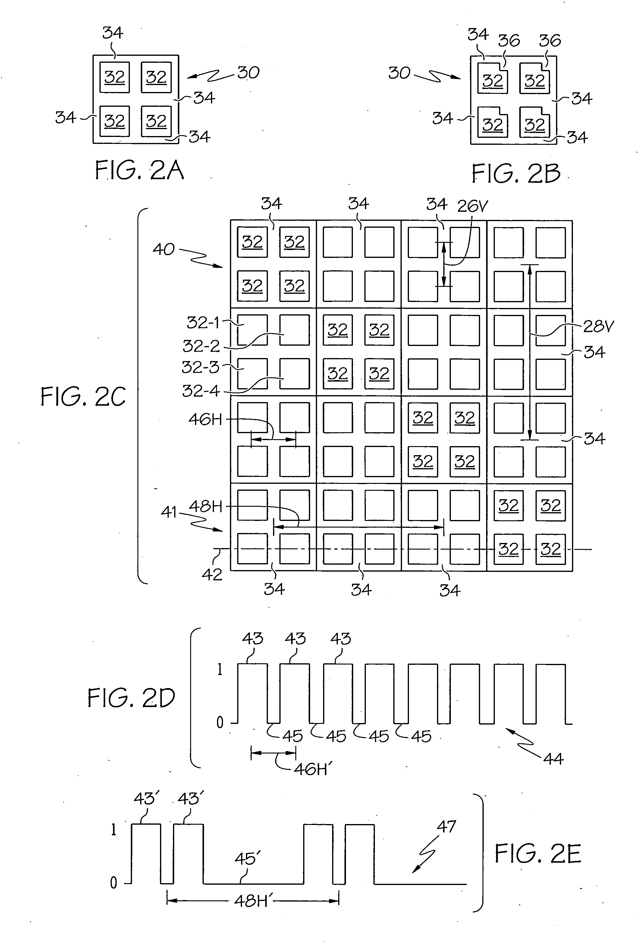
[0022]FIG. 2A is a simplified plan view, analogous to that of FIG. 1A of single pixel 30, FIG. 2C is a simplified plan view analogous to FIG. 1C of display 40 comprising a multiplicity of pixels 30 of the type shown in FIG. 2A, and FIGS. 2D-E are simplified plots analogous to FIGS. 1D-E of optical output 44, 47 of display 40 of FIG. 2C along line 42 (e.g., through row 41 of pixels 30 in display 40), all according to a first embodiment of ...


PUM

PropertyMeasurementUnit
transparentaaaaaaaaaa
aspect ratioaaaaaaaaaa

Abstract

Method and apparatus are provided for displaying an image to a viewer with reduced visual artifacts. The apparatus comprises a display panel for forming the image using an array of pixels with distributed active regions, and a viewing arrangement optically situated between the display panel and the viewer for transferring the image formed on the display panel to the viewer with limited angular pixel subtense. The distributed active regions of the pixels are desirably divided into at least two simultaneously switched portions at least partly separated by or surrounding a significant portion of the non-switchable region. First order spatial harmonics and associated artifacts are reduced by the distributed apertures and second order and higher harmonics are reduced by limiting the pixel subtense angle seen by the viewer. A significant reduction in visual artifacts arising from the periodic structure of the display panel is obtained.

Description

CROSS-REFERENCE TO RELATED APPLICATION [0001] This application claims the benefit of U.S. Provisional Application No. 60 / 639,876 filed Dec. 29, 2004.TECHNICAL FIELD [0002] The present invention generally relates to displays, and more particularly, to displays comprising an array of pixels with viewing optics. BACKGROUND [0003] There are many applications today that utilize displays formed from an array of individually addressable pixels. For convenience of description these are hereafter referred to as “pixeled displays.” The optical images to be presented by such displays are formed by activating various combinations of the individual pixels. An electrical or other signal causes portions of the various pixels to switch ON or OFF. The switched portions of the pixel may become transparent or opaque to a backlight or become luminous or dark, depending upon the type of pixel employed. In many display types, intermediate levels between full ON and OFF are also possible, for example by a...

Claims


Application Information

Patent Timeline
Patent Type & Authority Applications(United States)
IPC IPC(8): G02F1/1343
CPCG02B27/0025G02B27/01G02B27/0101G02B2027/012G02B2027/0123G02F1/133512G02F1/134336G02F2001/134345G02F2201/122G02F2201/15G02F2201/52G09G3/36G09G2300/0452G02F1/134345
Inventor LARSON, BRENT D.HAIM, ELIAS S.DUBIN, MATTHEW B.
Owner HONEYWELL INT INC
Why Eureka
Try Eureka