Microscope

Inactive Publication Date: 2006-06-29
CARL ZEISS JENA GMBH
View PDF5 Cites 7 Cited by
  • Summary
  • Abstract
  • Description
  • Claims
  • Application Information

AI Technical Summary

Benefits of technology

[0008] It is the primary object of the invention to minimize the influence of mechanical and thermal factors on the imaging quality and image transmission characteris

Problems solved by technology

During magnification, which can have values of up to 5000×, unwanted relative movements between the objective and the object to be magnified which can result, e.g., from building vibrations, are also magnified and lead to blurry images, loss of contrast and reduced resolution, especially at higher magnifications.
This usually leads to an amassing of material also at locations which do not necessarily help to improve the dynamic behavior but which have a negative result with respect to cost and weight.
Since the extent of modular expansion varies, dimen

Method used


Image

  • Microscope
  • Microscope
  • Microscope

Examples


Embodiment Construction

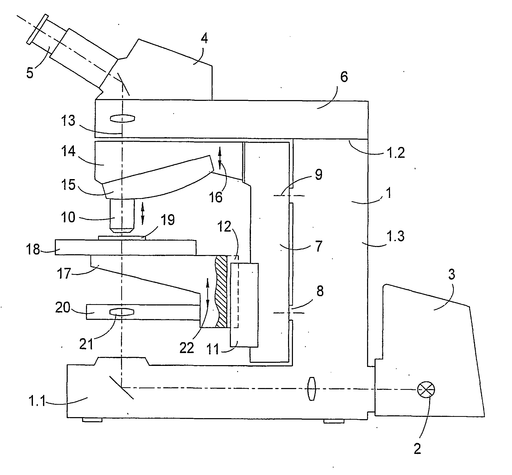
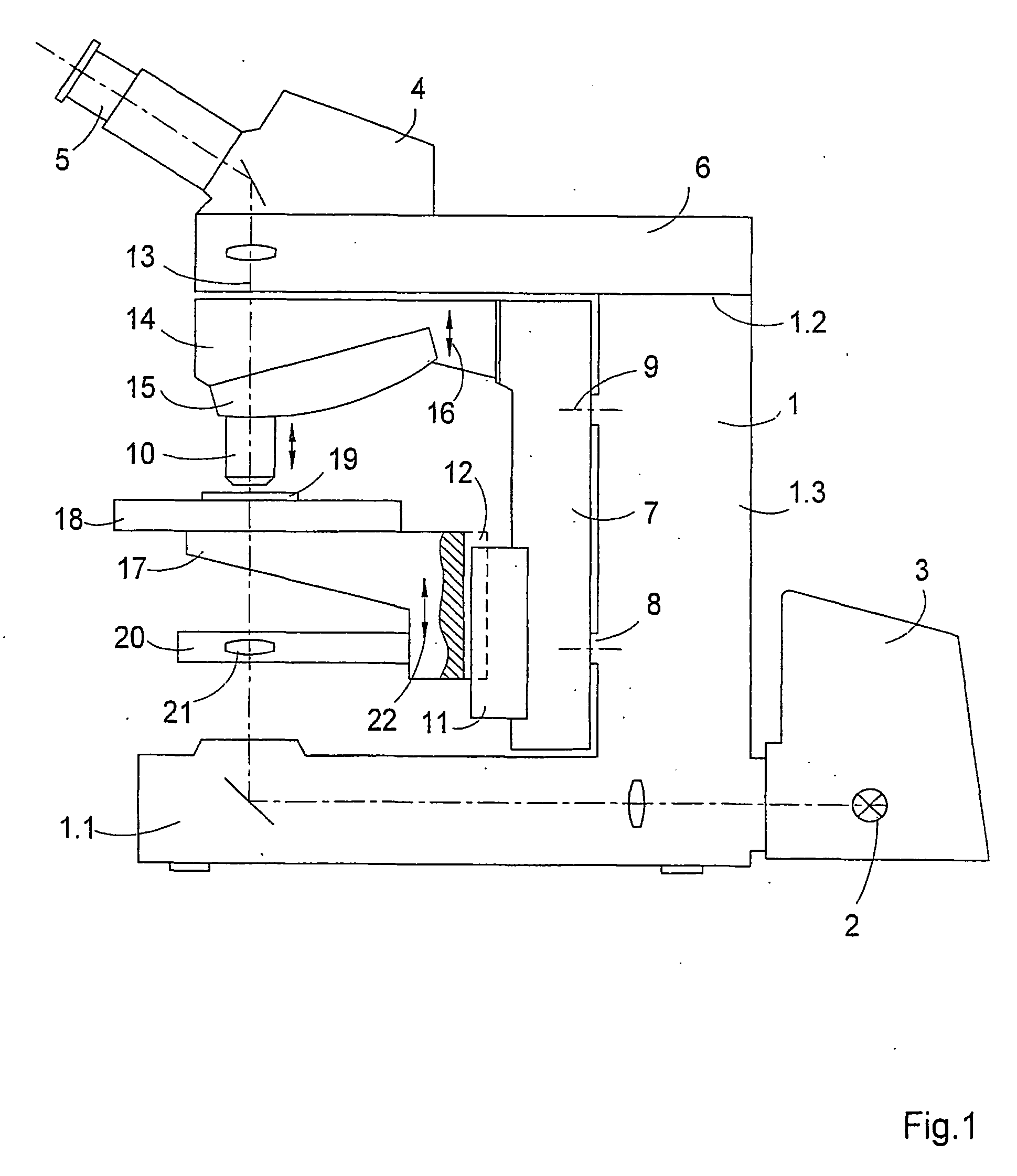
[0028]FIG. 1 is a highly simplified view showing the construction of an upright microscope which comprises a base body or stand 1 at which an illumination device 3 comprising a light source 2 is arranged in the bottom area 1.1. An arm 6 supporting an eyepiece receptacle 4 with an eyepiece 5 is arranged at the top end 1.2 of the stand 1. As can also be seen from FIG. 1, a supporting cell 7 which is optimized with respect to material and rigidity is advantageously rigidly arranged at the middle part 1.3 of the stand 1 as a separate assembly, preferably so as to contact projections 8 of the stand 1. In this connection, it is advantageous when the supporting cell 7 is arranged at the stand 1 rigidly, but also in such a way that it can be exchanged, i.e., detached, at any time in order to make changes on the microscope depending upon the task at hand. Screws, clamps or other suitable devices can be provided as fastening means 9, illustrated in dash-dot lines in FIG. 1. These fastening me...


PUM


Abstract

The invention is directed to a microscope comprising a base body or stand, a stage support, a guide for adjusting the stage support or an objective changer device with inserted objectives, and a stage for holding the object or specimen. In the microscope, a supporting cell is provided which is optimized with respect to material and rigidity and is connected to the stand rigidly but so as to be exchangeable. First assemblies for receiving, holding and adjusting the objective and second assemblies for positioning the object or specimen relative to the objective are arranged at the supporting cell. The first assemblies are designed as an objective changer device and/or as an objective focusing device, and the second assemblies comprise a stage support, a stage guide, and a stage.

Description

CROSS REFERENCE TO RELATED APPLICATIONS [0001] This application claims priority of International Application No. PCT / EP2003 / 013456, filed Nov. 28, 2003 and German Application No. 102 61 663.9, filed Dec. 20, 2002, the complete disclosures of which are hereby incorporated by reference. a) FIELD OF THE INVENTION [0002] The invention is directed to a microscope, in particular an optical microscope, and the mechanical construction thereof. b) DESCRIPTION OF THE RELATED ART [0003] Microscopes of whatever type of construction, whether upright or inverted, have the function of generating a magnified image of an object that can be observed and recorded. During magnification, which can have values of up to 5000×, unwanted relative movements between the objective and the object to be magnified which can result, e.g., from building vibrations, are also magnified and lead to blurry images, loss of contrast and reduced resolution, especially at higher magnifications. [0004] For this reason, the ...

Claims


Application Information

Patent Timeline
IPC IPC(8): G02B21/00G02B21/24
CPCG02B21/24
Inventor DIETZSCH, LEANDERKLARNER, ULLRICHTANDLER, HANSWAHL, HUBERT
Owner CARL ZEISS JENA GMBH
Why Eureka
Try Eureka