Geothermal power-generation system

Inactive Publication Date: 2012-01-05
MITSUBISHI HITACHIPOWER SYST LTD
View PDF5 Cites 5 Cited by
  • Summary
  • Abstract
  • Description
  • Claims
  • Application Information

AI Technical Summary

Benefits of technology

[0020]According to the geothermal power-generation system of the present invention, compressed air compressed by a compressor installed on the ground is sent to a piping in the ground, guided to a high temperature part in the ground, and the compressed air flowing in the piping is heated by geothermal heat. The compressed air thermally inflated in the ground is guided to the ground while heat-retained and introduced into a turbine fo

Problems solved by technology

When these gas components and chemical components are released on the ground, they can be a cause of pollution.
Furthermore, impurities need to be processed, resulting in increasing facility costs as well as causing th

Method used


Image

  • Geothermal power-generation system
  • Geothermal power-generation system
  • Geothermal power-generation system

Examples


embodiment

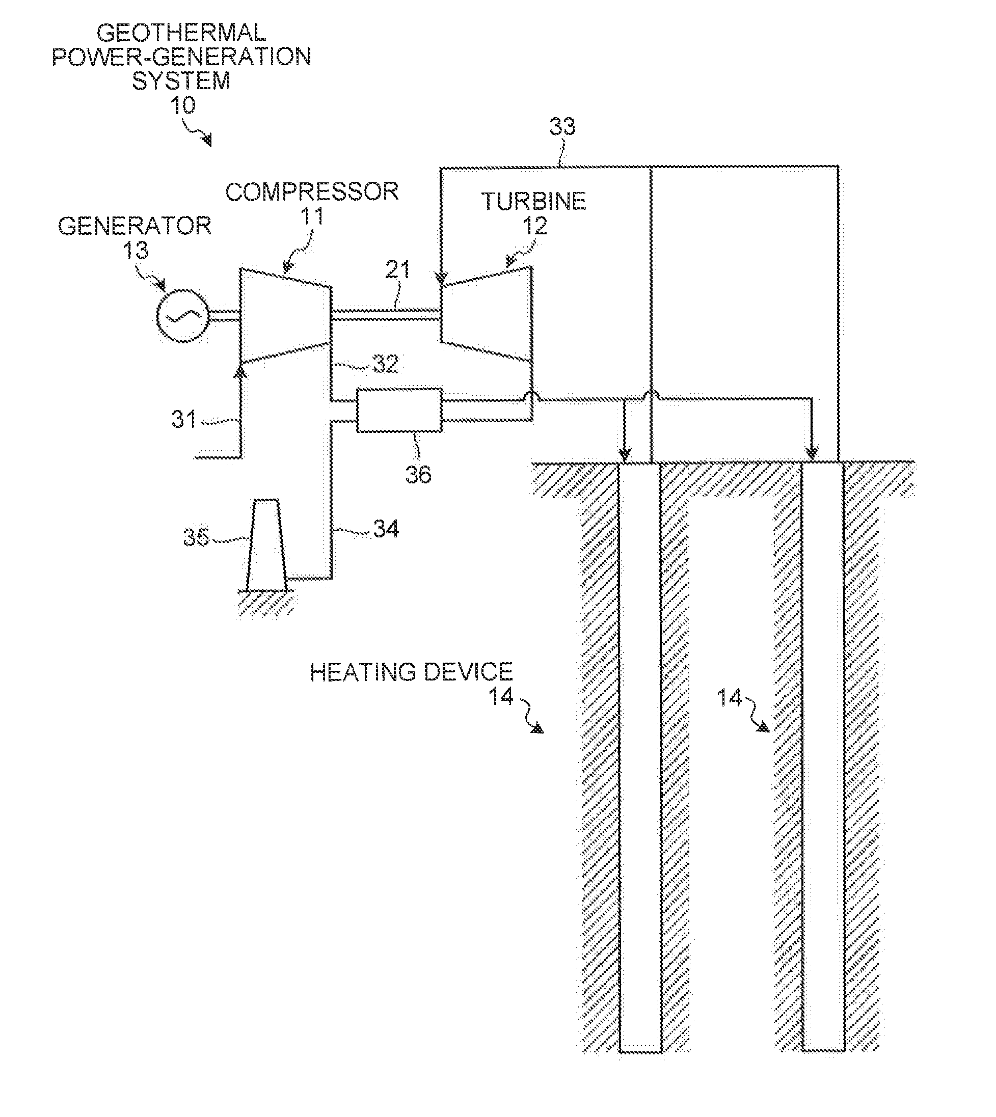
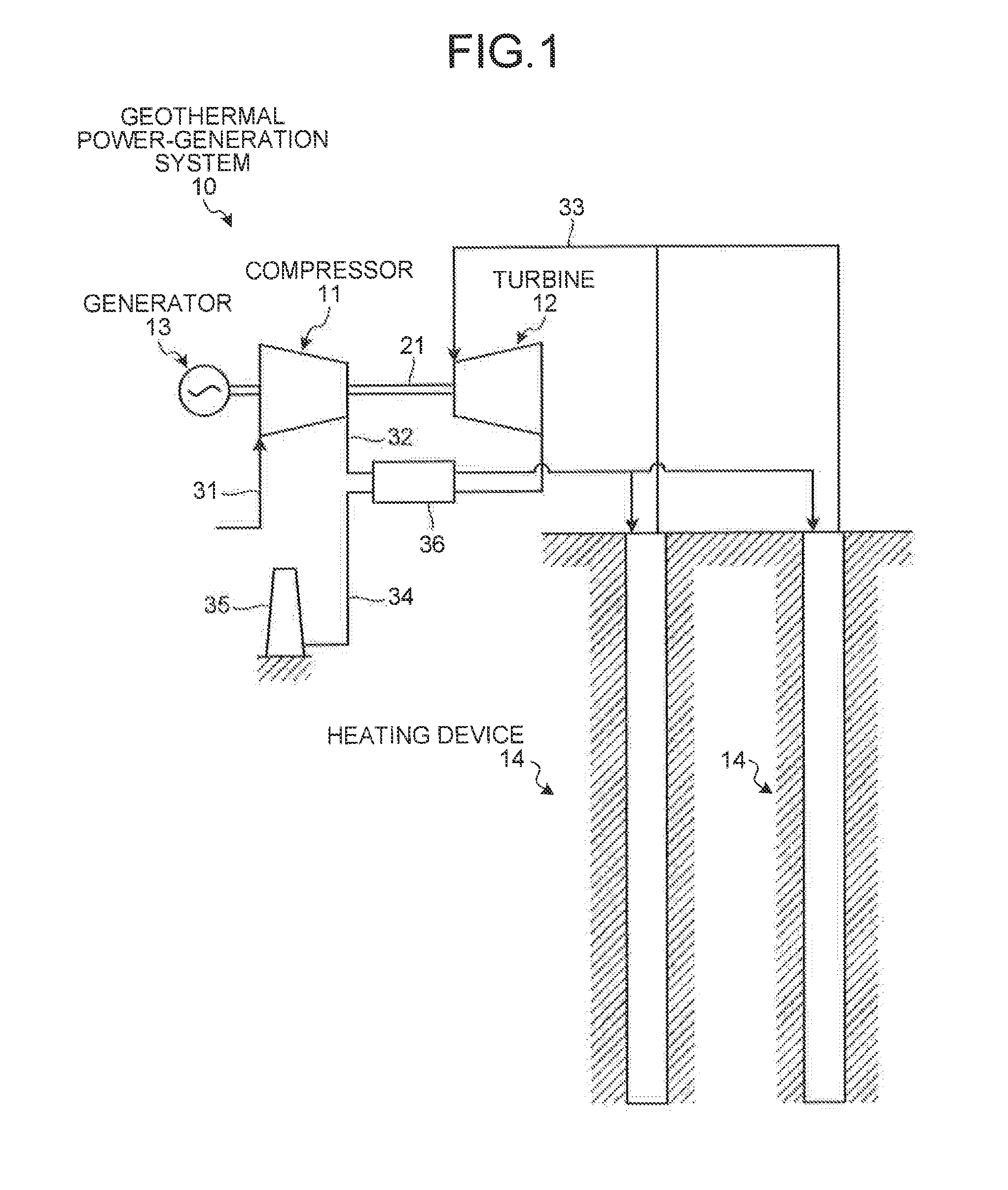
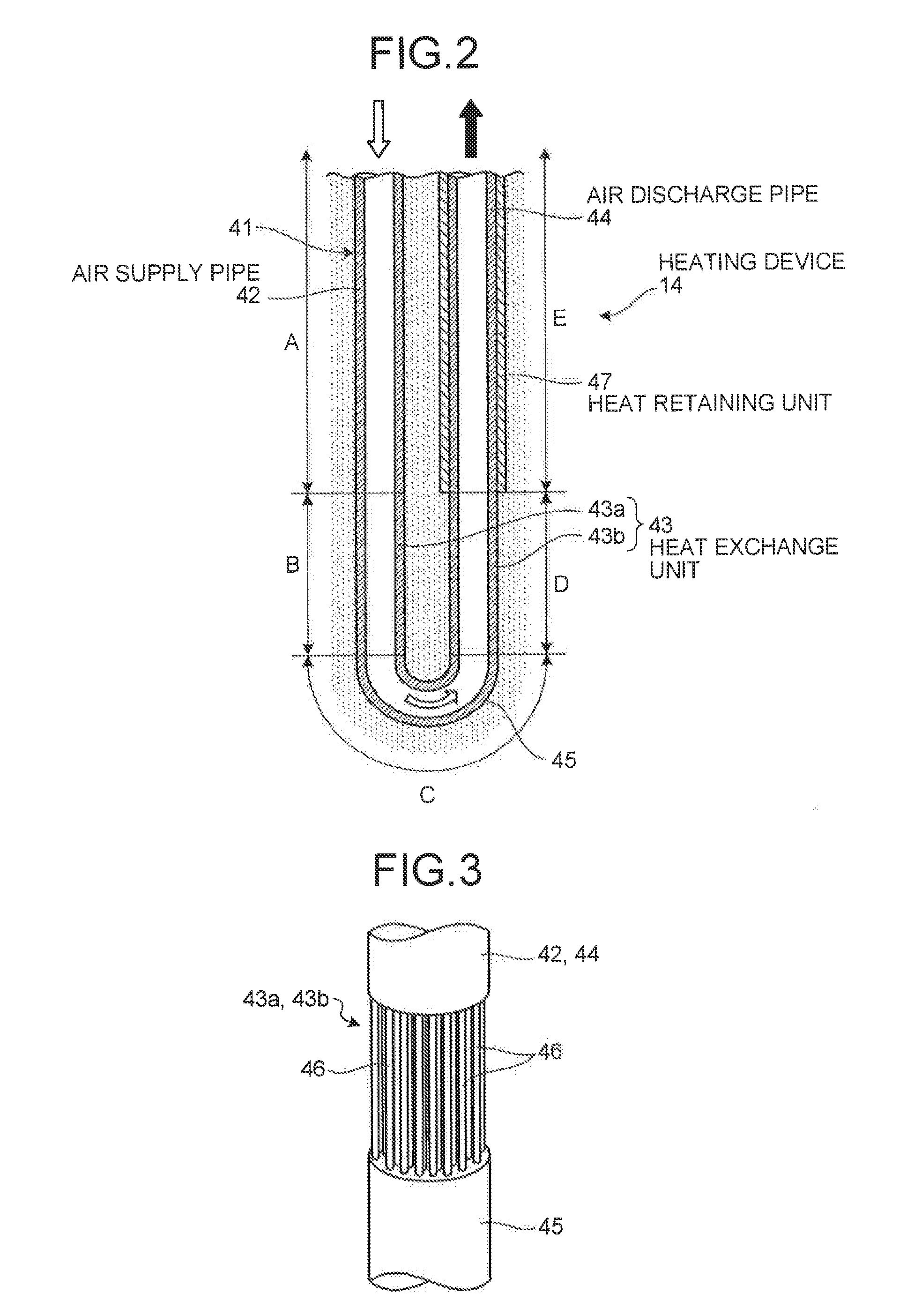
[0027]FIG. 1 is a schematic configuration diagram of a geothermal power-generation system according to an embodiment of the present invention, FIG. 2 is a schematic diagram of a bent part of a compressed air piping in the geothermal power-generation system according to the present embodiment, and FIGS. 3, 4, and 5 are schematic diagrams of modifications of a heat exchange unit in a compressed-air heating device according to the present embodiment.

[0028]The present embodiment provides a geothermal power-generation system that heats compressed air utilizing geothermal heat and drives and rotates a turbine by the heated compressed air for power generation. As shown in FIG. 1, a geothermal power-generation system 10 according the present embodiment is constituted by a compressor 11, a turbine 12, a generator 13, and a heating device 14. In this case, the compressor 11 and the turbine 12 constitute an air turbine.

[0029]In the air turbine, the compressor 11 is connected to the turbine 12 ...


PUM


Abstract

[Problem to be solved] To achieve a reduction in facility costs in a geothermal power-generation system.
[Solution] To provide a compressor 11 that compresses air, a heating device 14 that heats compressed air compressed by the compressor 11 by geothermal heat, a turbine 12 that obtains a rotational force by heated compressed air heated by the heating device 14, and a generator 13 that generates power by the rotational force inputted from the turbine 12.
[Chosen Drawing] FIG. 1

Description

TECHNICAL FIELD[0001]The present invention relates to a geothermal power-generation system that drives and rotates a turbine utilizing geothermal heat to generate power.BACKGROUND ART[0002]In normal power generation facilities using geothermal heat, the ground is excavated to a predetermined depth and a geothermal fluid in which vapor and hot water coexist under a high pressure in a deep underground is emitted to the ground. The geothermal fluid is separated into vapor and hot water by a vapor-water separator, and this separated vapor drives and rotates a turbine for power generation.[0003]However, the hot water and vapor taken out from a deep underground usually contain gas components such as carbon dioxide (CO2), hydrogen sulfide (H2S), ammonia (NH3), and methane (CH4). Sodium chloride (NaCl), boron (B), arsenic (As) and mercury (Hg), for example, are contained as chemical components depending on a temperature. When these gas components and chemical components are released on the ...

Claims


Application Information

Patent Timeline
IPC IPC(8): F03G7/00
CPCF03G7/04Y02E10/125F24J3/083F24T10/15Y02E10/10
Inventor NAKATANI, HIROMIKATO, JIN
Owner MITSUBISHI HITACHIPOWER SYST LTD
Why Eureka
Try Eureka