Orthopedic instrument

a technology for orthopedic instruments and burrs, which is applied in the field of improving orthopedic instruments, can solve the problems of large incisions to be made in limited space, the inability to adequately trim (or polish) burrs on the cut surface of the angle of the jaw, and the high risk of rotary apparatuses b>25/b> to b>29/b>, so as to reduce the number of persons required and ensure the effect of trimming

Inactive Publication Date: 2006-06-29
NIHON UNIVERSITY
View PDF6 Cites 86 Cited by
  • Summary
  • Abstract
  • Description
  • Claims
  • Application Information

AI Technical Summary

Benefits of technology

[0021] The present invention has been proposed in view of the above problem inherent to the conventional techniques and is intended to provide an orthopedic apparatus which enables safe trimming without damaging facial arteries / veins and nerves in the vicinity of the angle of jaw and without the need for making a large incision and allows a surgeon to perform trimming by one hand and reduces the number of persons required for an operation.

Problems solved by technology

However, the rotary apparatuses 25 to 29 are very likely to involve and damage blood vessels, nerves and other soft tissues.
Consequently, it is impossible to trim (or polish) burrs on the cut surface of the angle of jaw adequately.
However, since the orthopedic apparatus 40 as shown in FIGS. 21 and 22 is large, a problem arises that a large incision must be made in a limited space, namely the area between the gingivobuccal sulcus and the buccal mucosa, in order to allow insertion of its front end or reciprocating motion in the direction of arrow in FIG. 22 for trimming the cut surface of the angle of jaw.

Method used


Image

  • Orthopedic instrument
  • Orthopedic instrument
  • Orthopedic instrument

Examples


Embodiment Construction

[0054] Next, an embodiment of the present invention will be described in reference to the accompanying drawings.

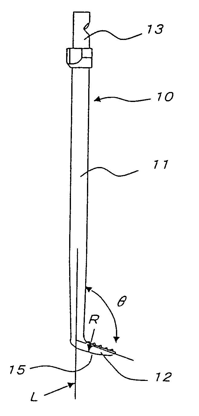
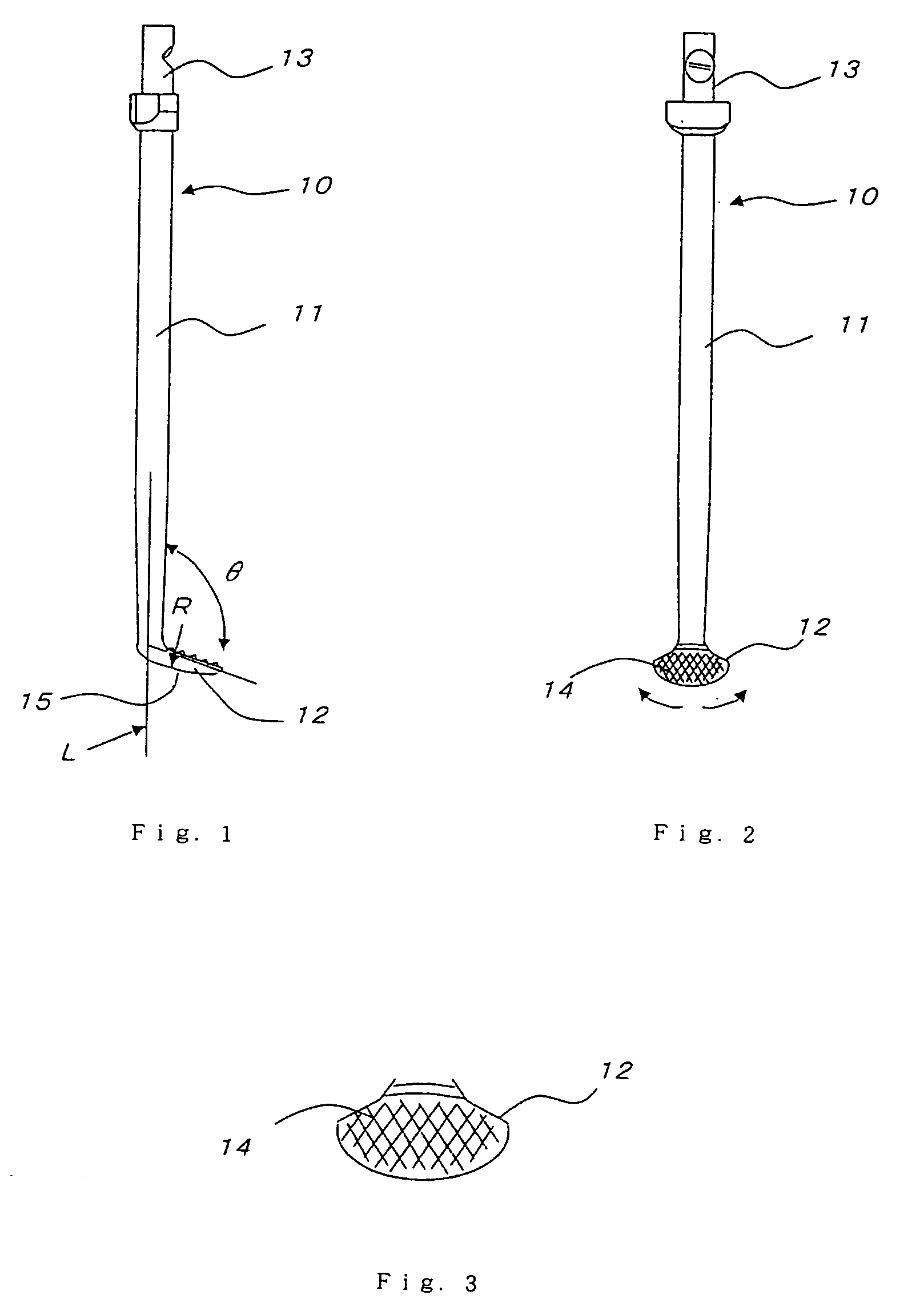
[0055]FIG. 1, FIG. 2 and FIG. 3 are respectively a side view and a front view showing a bone file as a separate unit according to an embodiment of the invention and an enlarged view of details of the fan-shaped member as its key part.

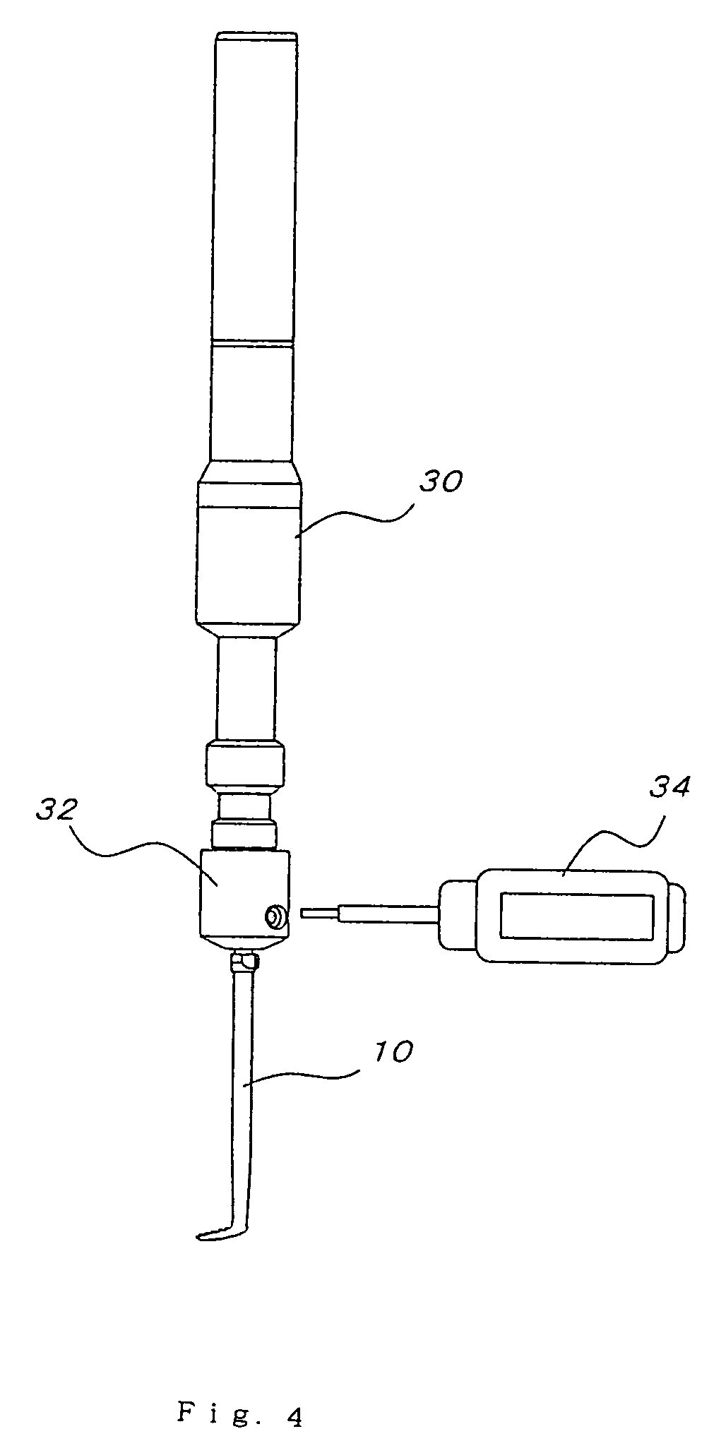
[0056] An orthopedic apparatus, for example a file 10, has a shank 11, a fan-shaped member 12 which is provided at the front end of the shank 11, and a coupling 13 which is provided at the rear end of the shank and is to be connected with a driving source (handpiece) 30 (stated later).

[0057] The fan-shaped member 12 is inclined by an angle of θ with respect to an axis line L and file ridges 14 are formed on the fan-shaped member 12's surface (reverse face) oriented toward the rear end of the shank.

[0058] The shank 11 is designed to oscillate clockwise and counterclockwise continuously by a driving source 30 (stated later). For a means for ...


PUM


Abstract

To provide an orthopedic apparatus with which a surgeon can perform a trimming operation safely without damaging blood vessels and nerves in the vicinity of an angle of jaw and without the need to make a large incision and a surgeon can perform a trimming operation by one hand with a smaller number of persons required for the operation.
The orthopedic apparatus has: a shank (11); a fan-shaped member (12) which is provided at the front end of the shank (11); and a coupling (13) which is provided at the rear end of the shank and to be connected to a driving source. The fan-shaped member (12) is inclined with respect to an extension (L) of the shank (inclination angle θ); file ridges (14) are formed on the fan-shaped member (12)'s surface (reverse side) which is oriented toward the rear end of the shank; and the shank (11) is constructed so as to rotate into a clockwise direction and a counterclockwise direction continuously.

Description

TECHNICAL FIELD [0001] The present invention relates to improvement of an orthopedic apparatus such as a file which is used to remove burrs generated on cut surfaces of bones or the like. BACKGROUND ART [0002] As shown in FIGS. 23 and 24, when an angle of jaw 3 (likened to “branchia”) of a lower jawbone 2 as a constituent of a skull 1A has overgrown because of hypertrophy of masseter muscle or when the amount of protrusion of the left angle of jaw 3 is not equal to that of the right angle of jaw 3, an operation to cut the overgrown part 3a of the lower jawbone 3 may be carried out. In FIGS. 23 and 24, numeral 1 represents a head which constitutes a skull. [0003] Many young people have a strong desire to make their face look smaller. With this background, an increasing number of people whose angles of jaw 3 are overgrown, namely “square-jawed” people, undergo an operation to remove the protruding part 3a of an angle of jaw 3 for a cosmetic purpose. [0004] For removing the protruding ...

Claims


Application Information

Patent Timeline
Patent Type & Authority Applications(United States)
IPC IPC(8): A61B17/16A61B17/56
CPCA61B17/1659A61B17/1673
Inventor IWANARI, SHINKICHI
Owner NIHON UNIVERSITY
Why Eureka
Try Eureka